Rhinestahl CTS FutureDrive NG+, User Manual
Looking for a comprehensive user manual for Rhinestahl CTS FutureDrive NG+? Look no further! Download our free manual from manualshive.com and unleash the full potential of this extraordinary product. Master every feature and functionality effortlessly with our detailed instructions, available at your fingertips.
Share
Download


Reviews:
No comments
Related manuals for FutureDrive NG+

Maltman 220
Brand: SOMMER Pages: 20

UT2010
Brand: Universal Tool Pages: 2

FX-601
Brand: Hakko Electronics Pages: 8

GS-202
Brand: Galaxy Pages: 11
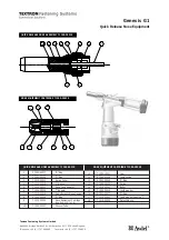
Textron Genesis G1
Brand: Avdel Pages: 2

HSP-176M-HD
Brand: Baileigh Industrial Pages: 44

Fat max
Brand: Stanley Pages: 32

KP15001
Brand: kincrome Pages: 10

BWR5122
Brand: BorMann Pages: 6

DG83231
Brand: STM Pages: 3

Locoloc SL-7NDK-SB
Brand: Loos & Co Pages: 12

RLK 608
Brand: RINGSPANN Pages: 6

HT-TRC
Brand: Cembre Pages: 24

B-FL750ND
Brand: Cembre Pages: 36

BP-301C
Brand: BluePoint Fasteners Pages: 13

ECE02015
Brand: Larzep Pages: 9

C00269
Brand: Band-it Pages: 3

JDP-20EVS-110
Brand: Jet Pages: 36


