


Sales department : Radio Frequency Systems GmbH
Kabelkamp 20, D-30179 Hannover (Germany)
•
Tel. +49-511 676-25 20
•
Fax +49-511 676-25 21
Plant: RFS France Trignac
•
Fax +33 02 40 90 41 43
1/8
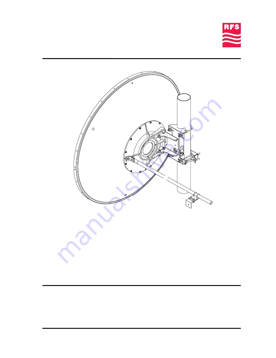
Installation Instructions
4 ft Antennas (with E-Mount)
PA, PAL, SP, SPF
PAX, SPX
NMT 552-01(e)
These Installation Instructions are valid for antennas in the following version :
•
Reflector Ø 1.2 m (4 ft)
•
Single
or
Dual
polarization
•
Pipe mount for installation on pipe
Ø 114 mm
•
Antenna offset to the left or to the right
•
Standard installation on
114 mm
pipe with offset to the left
•
Safety collar for easy installation
•
2 spindles for fine adjustment of
Elevation
of ± 15°
and
Azimuth
±
5°
•
Reflector without shroud
•
200 km/h
version :
With sway bar Ø 27 mm x 1.35 m
(mandatory)
It is important to mount the antenna exactly as described in this installation instruction.
The installed antenna shall be inspected once per year by qualified personnel.
RFS disclaims any responsibility for the result of improper or unsafe installation.
This installation instruction has been written for qualified, skilled personnel.
We reserve the right to alter details, especially with respect to technical improvement.


