


Rexroth IndraControl VCP 20
Industrial
Hydraulics
Electric Drives
and Controls
Linear Motion and
Assembly Technologies
Pneumatics
Service
Automation
Mobile
Hydraulics
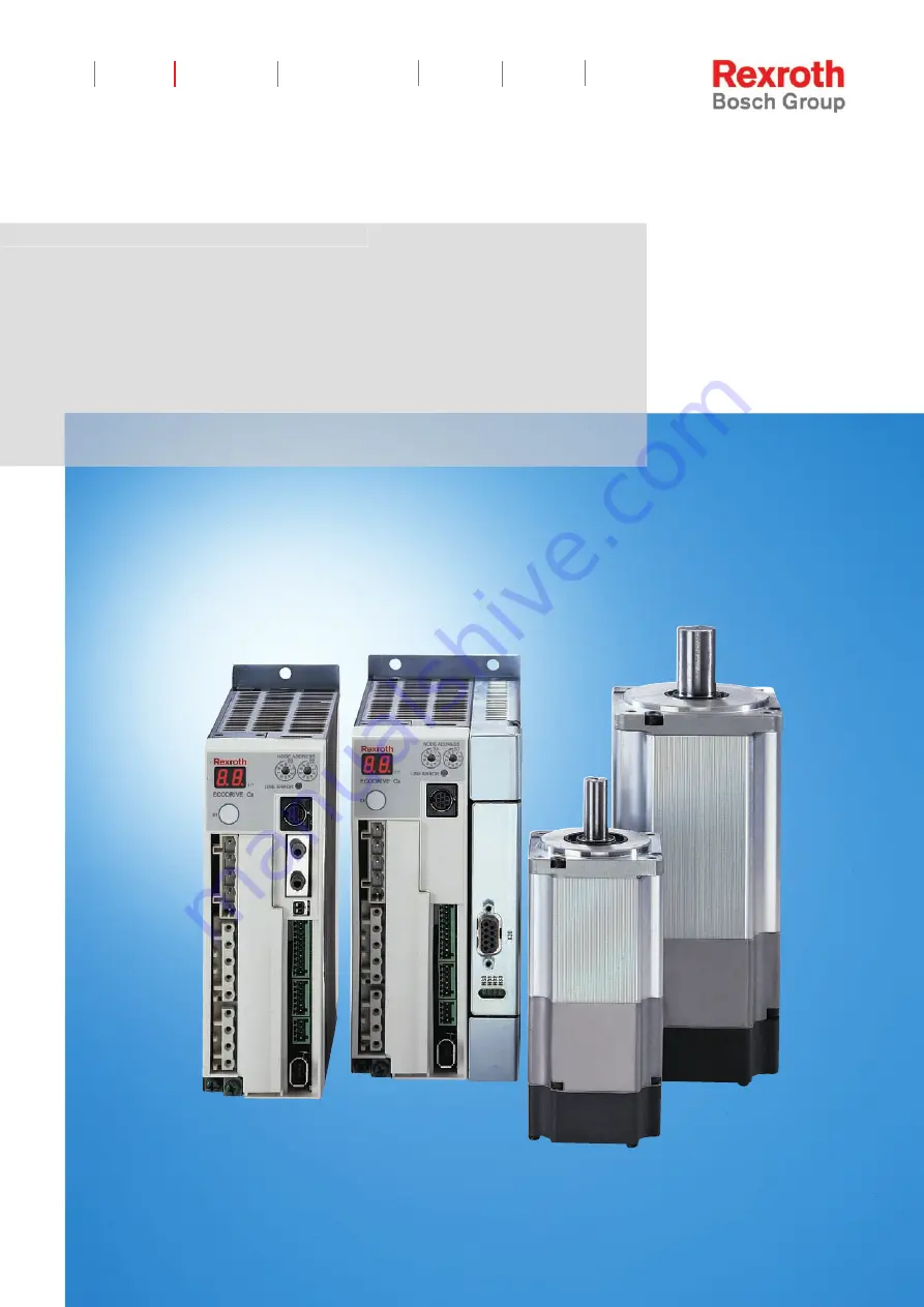
Rexroth EcoDrive Cs
Drives
R911295758
Edition 02
Project Planning Manual
Courtesy
of
CMA/Flodyne/Hydradyne
▪
Motion
Control
▪
Hydraulic
▪
Pneumatic
▪
Electrical
▪
Mechanical
▪
(800)
426-5480
▪
www.cmafh.com


