resideo Braukmann CBU145, Instructions Manual
The resideo Braukmann CBU145 Instructions Manual is a crucial tool for optimizing the performance of your product. Easily download the comprehensive manual for free from manualshive.com, ensuring you have all the necessary information at your fingertips. Don't miss out on maximizing your product's potential with this essential resource.
Share
Download


Reviews:
No comments
Related manuals for Braukmann CBU145
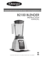
B2100
Brand: Omega Juicers Pages: 16

EL5363
Brand: Icron Pages: 17

Suprex SPX-7400 Series
Brand: Cypress Pages: 18

Activmix Premium 2103
Brand: eta Pages: 48

ME250IB
Brand: Calphalon Pages: 20

JEBT1241
Brand: Jata electro Pages: 20

RHBL1300
Brand: Russell Hobbs Pages: 16

14.99.3460
Brand: Value Pages: 4

RE6350
Brand: Linksys Pages: 5

WBT-1000
Brand: Planet Pages: 10

IPOE-E302
Brand: Planet Pages: 19

SV-500
Brand: Kuvings Pages: 10

DVS400
Brand: SMART-AVI Pages: 2

KNB-300O
Brand: Kuvinos Pages: 18

100.80001
Brand: Kenmore Pages: 8

68929
Brand: Kenmore Pages: 16

204101 - Elite 56 oz. Stand Blender
Brand: Kenmore Pages: 14

100.90001
Brand: Kenmore Pages: 8


