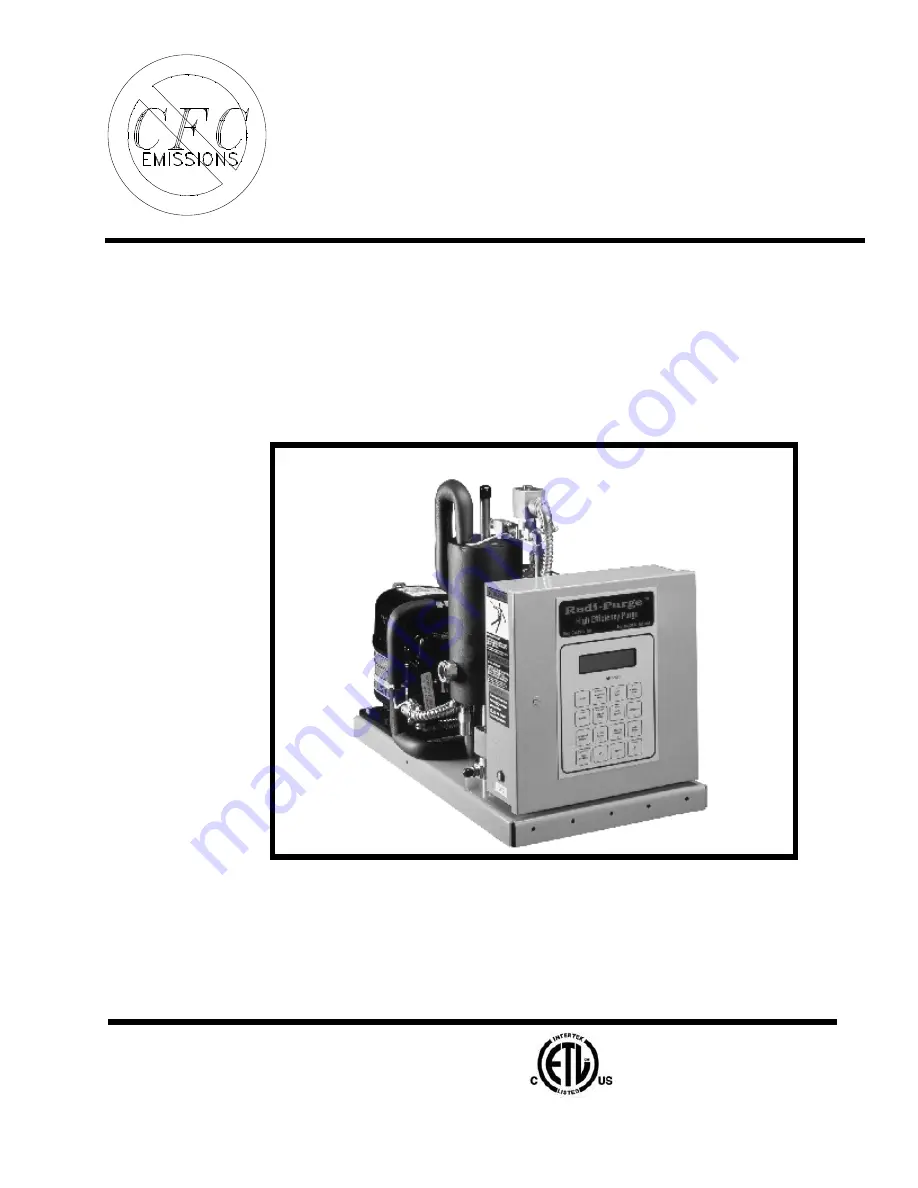
background image


Redi-Purge


Model PRG-113-C3 & C4


Microprocessor Controlled


Ultra High Efficiency  


             Purge Unit


                                  for


      Low Pressure Chillers 


Manufactured in accordance with 
ASHRAE Guidelines 3-1990 Sec. 4.7 and 
Standard 15-1992 Sec. 8.3, 8.7 and 10.4 

REDI CONTROLS, INC.


Installation, Operation & Maintenance Manual 


Literature File No. 1117-02 


ETL Listed 

3104248 

Summary of Contents for Redi-Purge PRG-113-C3

Page 1: ...igh Efficiency Purge Unit for Low Pressure Chillers Manufactured in accordance with ASHRAE Guidelines 3 1990 Sec 4 7 and Standard 15 1992 Sec 8 3 8 7 and 10 4 REDICONTROLS INC Installation Operation M...

Page 2: ...2 Revised Technically as of October 11 2013 1994 REDI CONTROLS INC GREENWOOD INDIANA...

Page 3: ...pment Warnings may appear in this manual or on the equipment Heed all Warnings Cautions Designed to alert you to situations that may result in damage to your equipment Personal safety and the proper o...

Page 4: ...4...

Page 5: ...nlet Line 13 Liquid Refrigerant Return Line 14 Refrigerant Line Installation Procedure 14 Pumpout Compressor Discharge Vent Line 15 Electrical Connections 15 Chiller Run Signal Wiring 15 Preliminary C...

Page 6: ...26 Purge Fault setting 26 Fault BYPASS setting 26 Drain Cycle setting sets LS1 liquid level switch make break hysterisis 27 Dip Switch S1 Settings 28 Dip switch S1 Security Lock 28 Dip switch S1 Cani...

Page 7: ...Purge 30 day average pumpout time while chiller is off Hrs Min 41 Log 2 Purge 30 day average pumpout time while chiller is on Hrs Min 41 Log 3 Purge Pumpout for Last 24 Hours Hrs Min 41 Log 4 Pumpout...

Page 8: ...ature Sensor TS3 56 Checking for Calibration 57 Table 2 Sensor Temperature vs Resistance 57 SERVICE TIPS 58 Purging after Internal Chiller Repairs or Servicing 58 Bypassing Pumpout Flow Restrictor 59...

Page 9: ...CFC or HCFC refrigerants The Purge together with the emission collection canister is designed to assure the highest efficiency in preventing refrigerant fr om escaping to the atmosphere This section d...

Page 10: ...t Each kit includes One Purge Unit One Installation Operation and Maintenance Manual One 1 2 inch ball valve Field Provided Items To be furnished by Purge Unit mounting hardware the installer Electric...

Page 11: ...nd remove all existing purge unit electrical connections from both the old purge unit and chiller control panel Disconnect the water lines to the old purge tank if applicable and cap off or remove The...

Page 12: ...ay be located at any convenient location on or near the chiller If you are replacing an old unit it can be locat ed in the same place as the existing system Mounting In a few cases some fabrication ma...

Page 13: ...or inlet line must be connected to both the cooling and auxiliary heat recovery condensers The entire length of both lines must slope toward either the purge unit or condensers Avoid sagging of the tu...

Page 14: ...ee gravity flow of liquid refrigerant back to the chiller 2 If used install the optional liquid line filter drier and the moisture indicating sight glass as shown in Figure 5 on page 18 The sight glas...

Page 15: ...odes Chiller Run Signal Wiring 1 For the typical purge unit installation refer to Electrical Schematic Figure 8 for appropriate chiller Run Signal wiring 2 However if the purge unit is being installed...

Page 16: ...TB1 1 TB1 6 should be 103 to 127 VAC and between TB1 3 TB1 6 should be 0 volts with chiller OFF and 103 to 127 VAC when chiller is ON 6 Check purge control panel LCD display the display should be disp...

Page 17: ...ASS Fault Toggle O n O ff Scroll ENTER Display SENSORS LOGs 7 Display 4 AUX Valve CLEAR LOGs STOP 1 Mode Compressor ADAPTIVE RESET 0 F unction SETTINGS 8 STATUS Display CLOCK Alarm SET 5 9 Mode DIAG 6...

Page 18: ...18 Figure 5 Flow Schematic and component location High Efficiency Purge with optional Emission Collection Canister Together system expels 0049 lbs CFC s or less per lb of air removed Atmosphere...

Page 19: ...k is cooled by the purge s air cooled condensing unit As the chiller s refrigerant condenses the pressure in the purge tank lowers drawing in additional vapor along with any air and moisture that may...

Page 20: ...id valve L3 see Figure 5 on page 18 Pumpout System The pumpout system consists of a 1 20 H P diaphragm pumpout compressor two pumpout solenoid valves and a flow restrictor device When sufficient air h...

Page 21: ...nsing saturation temperature drops too low For more information contact Equipment Servicing 3 Chiller evaporator pressure Pre Alarm PS1 option The chiller evaporator pressure Pre Alarm PS1 continuousl...

Page 22: ...itors the purge tank evaporating temperature Pumpout Solenoid Valves L4 L5 Pumpout solenoid valve L4 controls exhaust from the purge tank Valve L5 unloads the Pumpout Compressor C2 on start up see Fig...

Page 23: ...l equipment Terminal Block TB1 Terminal block TB1 is a terminal strip used for field wiring to the purge unit see Figure 4 on page 17 Control Transformer T1 Transformer T1 is a 12 volt power transform...

Page 24: ...h the rest of the manual then return to this section The LCD display should read System Ready Select Mode alternating with System Ready 00 00 AM clock display NOTE Upon initial power up purge display...

Page 25: ...m the factory with the security lock enabled see Dip switch S1 settings starting on page 28 NOTE SYSTEM IS NOW OPERATIONAL if you desire any other activity or understanding of the many capabilities su...

Page 26: ...sor movement keypad switches and to move the cursor beneath the position you want to change Use the numbered keypad switches to enter the desired value then press the ENTER key To change another opera...

Page 27: ...nk liquid level sight glass Liquid should accumulate until the liquid level reaches the top of the purge tank sight glass At this point liquid level switch LS1 contacts should close and energize drain...

Page 28: ...position 3 ON activates the Canister is Full Alarm when the emission collection canister is installed When using this setting purge operation will cease when Canister Full alarm occurs Dip switch S1...

Page 29: ...tory of all non condensable pumpout activity and automatically uses that recorded information to Duty Cycle start and stop future purge operation based upon its learned purging needs This minimizes bo...

Page 30: ...5 for additional information on fault indications Keypad Switches All purge unit functions are controlled via a multi function 16 switch keypad and a LCD display located on the front of the unit s ele...

Page 31: ...07 12 AM current clock time NOTE The SET CLOCK display will automatically be exited after 30 seconds of no Keypad activity STOP Keypad switch The STOP switch is used to stop purge operation Pressing...

Page 32: ...additional information see Operating Modes page 29 To enable the Adaptive mode press the Adaptive Switch The display will read On Adaptive indicating the purge is operating in the Adaptive mode The p...

Page 33: ...6 Purge Fault Time Fault Bypass Time Drain Cycle Time Chiller Cond Temp lock out set point when option installed Chiller Evaporator Pre Alarm set point when option installed BYPASS Keypad Switch Used...

Page 34: ...n when in the Bypass TIME PERIOD the Fault Bypass mode should be used sparingly and only if purge system is in proper working order DIAG Keypad Switch The DIAG mode can only be accessed by pressing th...

Page 35: ...with its associated LED Displayed Diagnostics Mode OUTPUTS D Compressor keypad switch press to activate press again to deactivate Used to activate compressor circuit which includes compressor C1 Comp...

Page 36: ...pad switch to scroll forward and backward one day at a time Displayed Chlr off Pumpout Day 00 H M 00 00 hours minutes To return to start of Log 1 press LOGs Keypad switch again To advance to next Log...

Page 37: ...ours following last chiller shutdown Displayed 3 Hour Test Pump out 00 00 hours minutes To advance to next Log press SCROLL To exit LOGs display press STATUS Log 5 Average daily chiller RUN time for l...

Page 38: ...se the or key pad switch to scroll forward and backward one day at a time Displayed total PumpOut day 00 h m 00 00 hours minutes To return to start of Log 8 press LOGs Keypad switch again To advance t...

Page 39: ...STATUS CLEAR LOGs Keypad Switch This switch is used to zero out data from certain LOGs To use the CLEAR LOGs keypad switch the Security Lock must be deactivated see Dip switch S1 Security Lock page 28...

Page 40: ...ational displays are viewed by pressing these keypad switches STATUS Display LOGs Display SENSOR Display Certain other miscellaneous displays will appear such as fault warning drain delays etc when an...

Page 41: ...rage period starts 3 hours after chiller has shut down It indicates the average daily purge pumpout time based on a thirty 30 day sliding window while the chiller is off Service pumpouts that occurred...

Page 42: ...the 3 hour period following chiller shutdown it may go into several drain back equalization cycles This is normal The purge is programmed to anticipate drainage imbalance conditions due to purge tank...

Page 43: ...ator a method of tracking purge operation during certain operator determined service intervals see interval log at the end of the explanation of LOGs keypad switch on page 39 for more information SENS...

Page 44: ...switch LS1 senses that the condensed refrigerant within the purge tank is not draining properly a Drain Back Equalization Cycle is initiated Maximum duration of the DRAIN BACK EQUALIZATION CYCLE is 1...

Page 45: ...Back Equalization Cycle terminates in less than two 2 minutes the purge unit will enter a two 2 minute Compressor Delay to prevent short cycling the compressor Displayed Drain Equalizing Compressor D...

Page 46: ...equalize and thus allow the purge tank to drain If the drain back equalization cycle fails to correct such pressure gradient imbalances or if there are any other problems affecting proper drainage su...

Page 47: ...ove any free standing water from the purge tank see Purge Tank Service beginning on page 49 Semi Annually Clean the air cooled condenser coils using compressed air or coil cleaner Clean the coil from...

Page 48: ...of this manual When the chiller is likely to contain a high level of moisture e g when starting a new chi ller or after chiller repairs the purge can be temporarily operated with the filter drier rem...

Page 49: ...g unit running observe the liquid level as it rises in the purge tank sight glass At the instant when the line of separation between the refrigerant level and the free standing water is at the top of...

Page 50: ...not seal off bubble tight When isolating the purge tank always use the chiller angle valve Next using the purge tank water drain angle valve pressurize the purge tank to approximately 2 psig using dry...

Page 51: ...VAC 1 L1 2 3 4 5 6 N J1 J2 C1 C2 L3 Ground Lug Ground L4 L5 ACI 1L ACI 2L LINE L1 12 VAC 12 VAC ACI 1H ACI 2H F1 1 Amp 250 V T1 PS1 LS1 Optional TS1 TS3 TS2 DCV Ground 5 VDC 10 Microprocessor Board Mo...

Page 52: ...om a Neutral MUST be supplied from the chiller control circuit and the J1 Jumper MUST be REMOVED Neutral Neutral 120 VAC 120 VAC L1 1 2 3 4 5 6 J2 N C1 L3 C2 Ground Lug Ground L4 L5 ACI 1L ACI 2L LINE...

Page 53: ...there is 12 volts DC between terminals labeled 12V and GND on the circuit board If either of these voltages are not present the Circuit Board is defective Replace Circuit Board The Purge is in the AU...

Page 54: ...ve Mode Normal Chiller off cycle operation No refrigerant level visible in purge tank sight glass Purge OFF in a drain back equalization cycle Liquid refrigerant may evaporate back to chiller during p...

Page 55: ...e sensor to points 4 and 5 be extremely careful not to disturb temperature sensors TS1 and TS2 With the purge condensing unit running read surface temperatures at points 2 and 3 in Figure 6 on page 19...

Page 56: ...minutes of operation the temperature at point 4 should settle out to approximately 5 F Both the meter and the display should indicate the same temperature If they do not correspond within 2 F the Temp...

Page 57: ...ration by measuring sensor resistance see Table below Table 2 Sensor Temperature vs Resistance Temperature Resistance F C Ohms 10 12 2 14 07K 20 6 6 10 41K 30 1 1 7 782K 40 4 4 5 874K 50 10 4 482K 60...

Page 58: ...the purge tank to cause the temperature Sensor TS1 to begin cycling the pumpout compressor This is the second phase of the operation and the pumpout compressor may cycle on and off frequently As the...

Page 59: ...following discussion is not intended to be all inclusive it does however serve to illustrate how various data and combinations of data may be used by the operator for managing a chillers refrigerant...

Page 60: ...leaked into the chiller some times cannot be completely removed while the chiller is running The only way this air can be removed is to operate the purge after the chiller shuts down When operated in...

Page 61: ...ter chiller shutdown A sudden change in the trend of this data which cannot be accounted for by a relative change in chiller operational patterns may indicate the need f or a system leak check or repa...

Page 62: ...3 4 5 6 7 8 9 1 0 11 1 2 1 3 14 1 5 1 6 17 1 8 1 9 20 2 1 2 2 23 2 4 2 5 26 2 7 2 8 29 30 3 1 D a y s o f t h e M o n t h Record displayed minutes of Pumpout Time below then plot to visually reflect t...

Page 63: ...1 2 3 4 5 6 7 8 9 1 0 11 1 2 1 3 14 1 5 1 6 17 1 8 1 9 20 2 1 2 2 23 2 4 2 5 26 2 7 2 8 29 30 3 1 D a y s o f t h e M o n t h Record displayed minutes of Pumpout Time below then plot to visually refle...

Page 64: ...D AY 1 2 3 4 5 6 7 8 9 1 0 11 1 2 1 3 14 1 5 1 6 17 1 8 1 9 20 2 1 2 2 23 2 4 2 5 26 2 7 2 8 29 30 3 1 D a y s o f t h e M o n t h Record displayed minutes of Pumpout Time below then plot to visually...

Page 65: ...AY 1 2 3 4 5 6 7 8 9 1 0 11 1 2 1 3 14 1 5 1 6 17 1 8 1 9 20 2 1 2 2 23 2 4 2 5 26 2 7 2 8 29 30 3 1 D a y s o f t h e M o n t h Record displayed minutes of Pumpout Time below then plot to visually re...

Page 66: ...in D AY 1 2 3 4 5 6 7 8 9 1 0 11 1 2 1 3 14 1 5 1 6 17 1 8 1 9 20 2 1 2 2 23 2 4 2 5 26 2 7 2 8 29 30 3 1 D a y s o f t h e M o n t h Record displayed minutes of Pumpout Time below then plot to visual...

Page 67: ...67...

Page 68: ...d by REDI CONTROLS l Failures of equipment due to abuse accident or negligence l Damages from or part failures due to equipment not being installed per REDI CONTROLS instructions per applicable codes...

Reviews: