


SECTION 1 MOUNTING & PIPING INSTALLATION
An APM is usually installed in the compressor room where
it can be monitored, but also may be installed outdoors
where temperatures below freezing are not anticipated.
The APM comes standard with a watertight NEMA 13 (IP65,
Category 2) control cabinet enclosure with sealed conduit
wiring. Any unused electrical entrances to the enclosure
must be sealed to protect electronics from moisture. A
NEMA 4 cabinet enclosure is available.
An optional valve package (VPM) for purger isolation is
available from Hansen. This consists of three welded
assemblies which include shut-off valves, gauge valves,
and mating flanges. An illustration detailing this optional
valve package is on page 12 (Figure 13).
FOUL GAS PIPING
Purging at several points, up to four with the APM, on the
high-pressure side of the system is the best method for
removing foul gas. Foul gas is refrigerant gas containing
some air or other noncondensibles. Several points should
be used because it is nearly impossible to predict where
noncondensible gas will accumulate in a system.
Even for multipoint purging, only one purge point should be
purged at a time. Connecting two purge points from two
condensers or receivers may result in gas flowing from one
condenser to another. This is due to an unequal pressure
drop, even though the differences in pressure drop are
very small, for example ¼ psig (0.02 bar). The result would
be that, even in the best of circumstances, only one point
is effectively purged. The best practice is to purge each
condenser and receiver circuit separately.
When utilizing multipoint purging, the purge point solenoid
valves can be manifolded into one foul gas line to the
purger. A ½" (13 mm) size line is the minimum and should
be pitched toward the purger to drain any condensed
liquid. Also, no liquid traps are allowed either before or
after the purge point solenoid valves (See Figure 2). The
foul gas line should not pass through cold areas where
INTRODUCTION
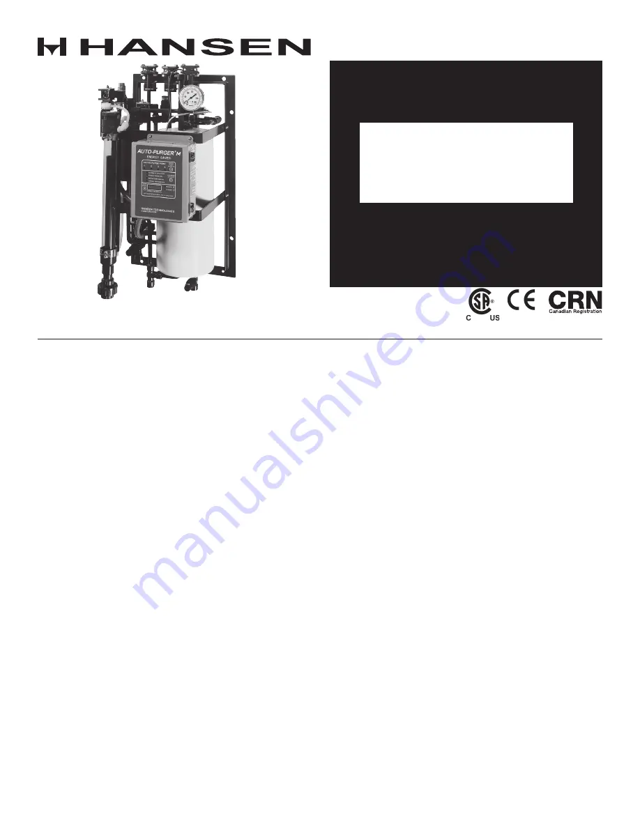
The AUTO-PURGER® M is a compact and totally automatic,
electronically-controlled, noncondensible gas refrigerant
purger for reducing condensing pressure, and thereby
saving electrical energy used by the refrigeration system.
This deluxe purger is preassembled, prewired, tested,
insulated, and includes an automatic water bubbler.
Installation requires piping the foul gas line, liquid line,
suction line, water line, drain line, and wiring the power
connection and the remote ½" (13 mm) port purge point
solenoid valves, which must be purchased separately. Up
to four (4) purge points can be controlled by this purger.
The AUTO-PURGER® M (APM) features welded piping
and watertight electrical construction. The APM meets
the requirements of the Canadian Standards Association
(CSA certified).
A typical APM installed in a plant with normal-entering
noncondensible loads will handle up to a 200 ton (700 kW)
system. Each purge point will be active between 10 and 30
minutes, depending on the noncondensible gas presence
(mostly air) and the purger mode of operation.
Model APMF AUTO-PURGERS are for use in halocarbon
refrigeration systems. The installation and operation of
these AUTO-PURGERS are similar to that of an ammonia
AUTO-PURGER M. See page 13 for additional details.
MOUNTING INSTRUCTIONS
Mount the APM straight and securely on a wall or sturdy
steel channels capable of supporting 350 lbs (160 Kg). Eight
mounting holes in the frame are provided to support the
purger (See Figure 1). The APM should be located in an
accessible area, but away from the movement of equipment
that could accidentally damage the purger. Elevation with
respect to condensers or high-pressure receivers is not
critical, however, purge point solenoid valves must be
above the purger.
Specifications, Applications,
Service Instructions & Parts
AUTO-PURGER
®
M
“Energy Saver”
Compact, Non-condensible
Gas (Air) Purger
Bulletin APM-001e
AUG 2015
For Models APM & APMF
Model APM


