


INSTALLATION & OPERATING
INSTRUCTIONS
CATALOG NO. 2000.50AI
Effective: 09-28-12
Replaces: 06-27-11
P/N 240035 Rev. 36
This manual should be maintained in legible condition and kept adjacent to the heater or in a safe place for future
reference.
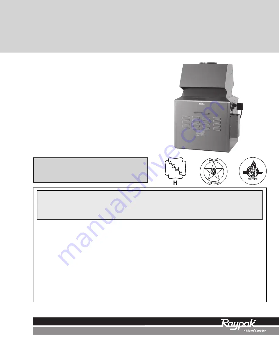
Models 181–4001
Type H
WHAT TO DO IF YOU SMELL GAS:
• Do not try to light any appliance.
• Do not touch any electrical switch; do not use any phone in your building.
• Immediately call your gas supplier from a neighbor's phone. Follow the gas
supplier's instructions.
• If you cannot reach your gas supplier, call the fire department.
WARNING:
Improper installation, adjustment, alteration, service or maintenance can
cause property damage, personal injury or loss of life. Refer to this manual.
Installation and service must be performed by a qualified installer, service agency or
the gas supplier.
FOR YOUR SAFETY:
Do not store or use gasoline or other flammable vapors and
liquids or other combustible materials in the vicinity of this or any other appliance. To
do so may result in an explosion or fire.
Installation and service must be performed by a qualified installer, service agency or
the gas supplier.
Raytherm™
Heating
Boilers


