background image


                                                  OWNER'S MANUAL


Mobile Audio/Video System
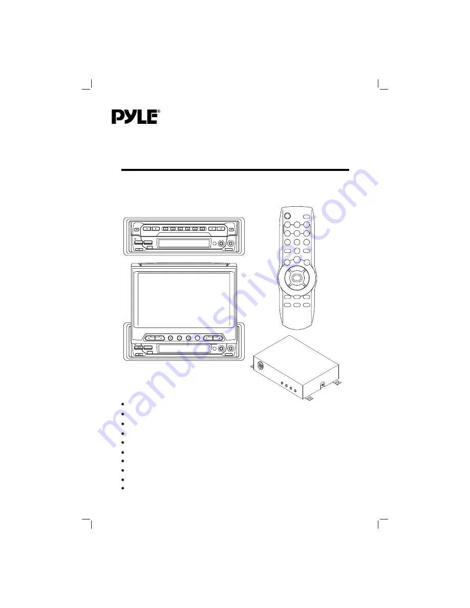
PLTV65R

www.pyleaudio.com

PLL Synthesizer Stereo Radio 
Built In Amplifier 
Vertical Adjustable And Horizontal Rotatable Panel 
Automatically Memory Storing   
TFT Monitor   
Remote Control   
Optional TV Tuner (Separate Box) 
CD Changer Control 

AM/FM/MPX/TV-Tuner 

4 x 40 Watts 

Summary of Contents for PLTV65R

Page 1: ...ww pyleaudio com PLL Synthesizer Stereo Radio Built In Amplifier Vertical AdjustableAnd Horizontal Rotatable Panel Automatically Memory Storing TFT Monitor Remote Control Optional TV Tuner Separate Box CD Changer Control AM FM MPX TV Tuner 4 x 40 Watts ...

Page 2: ...ching to radio mode Selecting the frequency band Selecting station Setting memory Automatic memory storing program scanning Local distant Mono stereo Scan CDC operation Switching to CDC mode Selecting tracks Pausing playing Previewing all tracks Repeating the same track Playing all tracks in random Selecting disc Operating when the monitor stretching out Menu control operation in radio mode Menu c...

Page 3: ... and servicing This unit doesn t contain any parts that can be repaired by the user 2 The monitor is operated automatically Do not draw the monitor out or turn it upward or downward manually Otherwise the mechanism construction may be harmed to some degree 3 When you operate the monitor with the remote handset do not touch the monitor by your hands It may harm your fingers CAUTION Please read and ...

Page 4: ...UNT This unit be can properly installed either from Front conventional DIN Front mount or Rear DIN Rear mount installation utilizing threaded screw holes at the sides of the unit chassis For details refer to the following illustrated installation methods 4 TAKE OUT SCREW BEFORE INSTALLATION Before install the unit please remove the two screws on the back of the unit Take out screw before installat...

Page 5: ... necessary bend the metal strap to fit your vehicle s mounting area Then use the supplied hardware 7 8 5 6 place Tabs Screwdriver Sleeve Dashboard any wires or cables Mounting Bolt Plain Washer Tapping Screw Metal Strap Spring Washer Hex Nut Tapping Screw 5x25mm and Plain Washer to attach the other end of metal strap to a solid metal part of the vehicle under the dashboard This strap also helps en...

Page 6: ...io mounting bracket with the factory radio mounting bracket tighten the screws 5x5mm at 2 places on each side 5 When fix the factory radio mounting bracket with the screws use s standard tipped screwdriver to open the tabs of the car radio mounting bracket to make them fit into theholes in the factory radio mounting bracket 6 3 4 1 5 2 ...

Page 7: ...N WHITE WHITE BLACK REAR Rch SPEAKER BRAKE 2 SPEAKER FRONT Rch POWER ANTENNA EXTERNAL REMOTE CONTRL with the 13 pin din Jack To the TV unit GREY OPTIONAL AV OUT ANTENNA CONNECTOR BLACK AV2 IN MAIN UNIT YELLOW SYNC IN BLUE GREEN RED R G B IN CONNECTOR SOCKET CD CHANGER Note The Brake 1 wire is designed to connect to the ground wire and the Brake 2 wire is designed to connect to CPU Be sure that the...

Page 8: ...8 OPERATION LOCATION AND FUNCTION OF KEYS Fig A 23 22 5 25 27 26 Fig B 6 9 8 1 7 15 28 29 30 31 32 33 18 14 10 13 17 11 3 2 16 12 4 19 20 21 24 ...

Page 9: ...y 15 M1 M6 16 MO ST 17 AUDIO 1 IN 18 VIDEO 1 IN 19 MENU 20 DSP 21 TV AV 22 VOLUME 23 VOLUME 24 CHANNEL 25 CHANNEL 26 IR 27 4 3 16 9 Selector 28 PAU For CDC Version Only 29 INT For CDC Version Only 30 RPT For CDC Version Only 31 RDM For CDC Version Only 32 CD For CDC Version Only 33 CD For CDC Version Only 34 POWER 35 OPEN 36 0 9 Numeric Button 37 M1 M6 38 LOC 39 SCAN 40 BAND 41 TV AV 42 MODE 43 MU...

Page 10: ...te control to turn the monitor upward or downward at fine steps to get a desired viewing angle And you can rotate the monitor left and right from the central viewing position at a certain angle range manually Don t rotate the monitor forcibly to avoid mechanical damage Fig 2 Return the monitor to the central viewing position then press OPEN CLOSE button 2 on the front panel or press OPEN button 35...

Page 11: ...do not operate Error symbol on the display Note When the monitor stretches out and on the central viewing position activate the reset button 9 the monitor will turn downward and draw in automatically OPERATING WHEN THE MONITOR NOT STRETCHING OUT When the monitor doesn t stretch out the front panel of the unit is in state A see Fig A you can operate the unit following the instructions below Sound m...

Page 12: ...ear and the LCD enter into frequency showing if you don t operate it Then you press DISP button again the LCD remains the previous state and the clock will not appear You should press DISP button once again to display the clock Radio operation Switching to radio mode Press MODE button 12 on the front panel or MODE button 42 on the remote control to select radio mode the radio mode appears in the d...

Page 13: ...to scan mode which scanning to higher frequency station with receivable signal and keep on each station for several seconds At this time press any one of the buttons 15 on the front panel or 37 on remote control the current scanned station will be stored into the corresponding number button then it keeps on scanning other stations CDC operation Switching to CDC mode Press MODE button 12 on the fro...

Page 14: ...ust the selected item The corresponding value will show on the display Press any one of the Radio Preset buttons 1 6 37 to retrieve a station between M1 M6 The corresponding number will show on the display Press LOC button 38 on remote contro lto select between LOC and DX Press MO ST button 16 on the front panel or ST MO button 53 on remote control to select MONO or STEREO FM1 98 10 MHz MONO LOC V...

Page 15: ...o move to the next track TV operation when the unit is connected to other TV unit through the cable with the 13 pin din plug on each terminal Switching to TV mode Press MODE button 12 on the front panel or MODE button 42 on remote control to select TV mode and the memory channel will show on the TFT display 5 Selecting receiving mode In TV mode press TV AV button 21 or 41 to select among TV AV1 AV...

Page 16: ...display 5 BRIGHT COLOR Press TUN CH buttons 46 to select the item upward or downward Then press VOL buttons 47 to adjust the selected item The corresponding value will show on the display Volume adjustment Press VOLUME buttons 23 22 or VOL buttons 47 to adjust volume level Screen display Press DSP button 20 on the front panel or DISP button 44 on remote control to display the current status such a...

Page 17: ... Drain 15 Ampere max TV Monitor Screen Size 6 5 TFT Frequency Coverage 87 5 to 107 9 MHz Sensitivity S N 30dB 4 V Image Rejection 45dB Stereo Separation 25dB AM Frequency Coverage 530 to 1720 kHz Sensitivity S N 20dB 36 dBu Image Rejection 45 dB RADIO FM Resolution 1440 x 234 dots TV Sensitivity 45dB V CH25 in average ...

Page 18: ...MOBILE TV TUNER UNIT 18 ...

Page 19: ...2 1 POWER INDICATOR LIGHT When the unit is connected to the other system with the 13 pin din cable and the other system turns on the power indicator light 1 will be illuminated red and the unit turns on 2 DIVERSITY ANTENNAINPUT There are four antenna input jacks 2 for antenna input 3 MONITOR Use one 13 pin cable to connect the unit and other system One terminal is connected to the 13 pin din socke...

Page 20: ...www pyleaudio com 88 T1690 04 ...

Reviews: