1
Application:
This thermostat is a 120VAC Heating and Cooling Digital Temperature
Control. It is designed for use on 4-pipe and 2-pipe fan coil systems
operating at 120VAC. Switching of load circuits is through relay
contacts, allowing the control to switch pilot duty and fan loads. Fan
cycles on/off automatically with calls for heating or cooling. Two
speed direct drive capability for fan motors up to 1/6 HP. This
thermostat operates from a single setpoint with automatic changeover
from heating to cooling. There is built in programming to alter the
control characteristics to suit energy conservation needs.
Installation Notice:
This high performance digital thermostat is designed to provide many
years of superior comfort control when properly installed and maintained.
To achieve maximum performance, this device is designed to draw
room air into itself continuously. Reasonable care must therefore be
taken with regard to air quality at the time of installation as well as
during periods of normal use, see operating conditions below.
Operating Conditions:
The electronic mechanisms incorporated within this unit REQUIRE
operating conditions similar to other electronic devices intended for
INDOOR USE ONLY, such as would be acceptable for TV and similar
household appliances. Relative humidity must be less than 95% and
the atmosphere must be non-condensing. For operation in bathrooms,
shower or pool areas, outdoor entryways, greenhouses and similar
applications, order HSK-4120U or NPK-4120U. These products
include protection for coastal/tropical applications, therefore they are
suitable for use in high humidity environments. Air quality must be
maintained FREE of heavy dust or debris which may infiltrate the
interior of this device. Installation in any space which is unfinished
or undergoing repainting or general rehabilitation is also considered
product abuse. This device should be removed from service during
any local construction activity.
Cleaning:
This device incorporates a high impact polycarbonate enclosure which
is easily cleaned with a dry cloth or vacuum brush. Occasional soiling
may be cleaned with a soft cloth lightly dampened with water and/or
mild cleaning solution. IN NO CASE should this device be directly
sprayed with or exposed to free flowing liquids, including water, which
could penetrate its interior.
FAILURE TO OBSERVE ANY OF THE ABOVE CONDITIONS OF USE
WILL COMPLETELY VOID THE SUPPLIER WARRANTY.
CAUTION
MAKE SURE UNIT IS PROPERLY CONNECTED. DAMAGE TO THE
DIGITAL CONTROL CAN BE CAUSED BY MISWIRING, WHICH WILL
VOID THE WARRANTY. FOR SAFETY REASONS ALWAYS USE
WIRE NUTS ON ALL WIRE CONNECTIONS!!!
User Note: The top of this unit will become warm to the touch. This is a
normal operation. Internal heating is employed to continuously convect
air upward through the thermostat, thereby improving room air temperature
measurement. Direct conflict with a downward ceiling fan or system fan air
flow may result in false temperature reading. Locate thermostat to avoid
interference.
Specifications:
Temperature Monitor Range:
32.0°F to 99.9°F (0.0°C to 37.7°C)
Setpoint Range:
60.0°F to 85.0°F (15.5°C to 29.5°C)
*Setpoint Default:
72.0°F (22.0°C)
*Comfort Conditioning Limit Defaults:
65.0°F (18.5°C) cooling
85.0°F
(29.5°C)
heating
Display Format:
Liquid Crystal Display (LCD)
Sampling Rate:
Every 5 seconds
Accuracy:
± 1°F (0.5°C)
Power Source:
120VAC
Load Rating:
2 Amps heat/cool, 1/6 HP fan
*Fan Control: Selectable:
Auto cycle, Low, High
Heat/Cool Control:
1 heat and 1 cool circuit (2 Amps pilot duty)
*Default Temperature Extreme Prevention Limits:
Maintains room temperature between 60.0°F and 85.0°F
(15.5°C and 29.5°C) when thermostat is in economy mode
*Fan Purge Timer:
30 seconds default
programmable 0 (off) to 180 seconds
Anti-short Cycle:
3 minute hold in no call state at all times
*Cycle Rate:
8 cycles per hour
*See Field Programming Instructions
Old thermostat
wire function
Power Feed
Neutral
Heat
Cool
Low Fan
Medium Fan
High Fan
Cable
wire color
HIGH
LOW
AUTO
ECONOMY
°F/°C
Decrease
Temperature
Switches between
°F and °C
Selects
Fan/Economy
Function
Increase
Temperature
4-Pipe Fan Coil Installation:
This device should be installed and serviced by a qualified technician.
Junction box mounting is highly recommended.
1. Caution:
Make sure that power has been disconnected.
2.
All wiring must comply with applicable codes and ordinances.
3.
A thorough check-out of the system should be made after
installation is complete.
4.
If fan motor is larger than 1/6 HP and/or electric heaters are used
for heating, additional power relays will be required.
5.
If retrofitting old thermostat, remove old thermostat from the
junction box, carefully noting the wire connections on the old unit.
Record wire color and terminal legends in spaces provided.
Disconnect old thermostat and remove any existing backplate or
mounting plate.
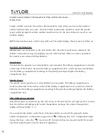
Retrofitting with Existing Control Wiring:
Most 3 speed fan system's control wiring
is sufficient to connect this 2 speed
thermostat without adding a neutral wire.
This connection is achieved by using the
third fan speed wire as a neutral.
Disconnect the unused fan speed wire
from the fan motor and connect it to
*Neutral. Be sure to insulate the unused
fan motor wire to prevent shorts. At the
thermostat, connect the unused fan
speed wire (now neutral) to the thermostat.
X
Unused Speed
Low Speed
High Speed
High Fan
(Yellow w/red str)
Low Fan
(Yellow)
Neutral (White)
*Neutral
Cut Wire
Cool (Blue)
Heat (Red)
Load Feed (Orange)
Control Feed (Black)
Fan
Motor
Figure 1
Installation and Operating Instructions
HS/HSK-4120U
NP/NPK-4120U