


PRONAR Sp. z o.o.
17-210 NAREW, UL. MICKIEWICZA 101A, PODLASKIE PROVINCE
tel.:
+48 085 681 63 29
+48 085 681 64 29
+48 085 681 63 81
+48 085 681 63 82
fax:
+48 085 681 63 83
+48 085 682 71 10
www.pronar.pl
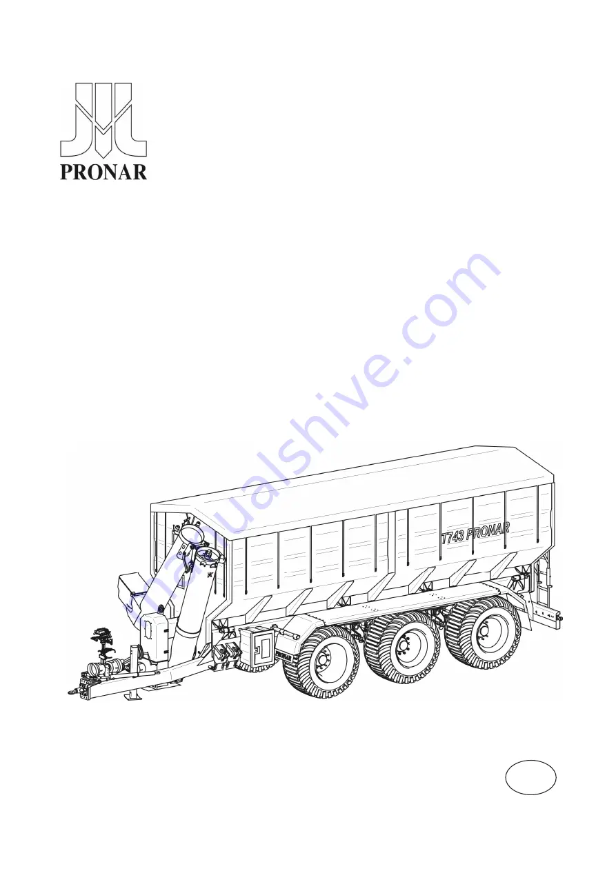
OPERATOR'S MANUAL
AGRICULTURAL TRAILER
PRONAR T743
TRANSLATION OF THE ORIGINAL COPY OF THE MANUAL
ISSUE 2A-01-2010
PUBLICATION NO 205N-00000000-UM
EN
Summary of Contents for T743
Page 2: ......
Page 6: ......
Page 11: ......
Page 12: ...SECTION 1 BASIC INFORMATION ...
Page 25: ...Pronar T743 SECTION 1 1 14 ...
Page 26: ...SECTION 2 SAFETY ADVICE ...
Page 46: ...SECTION 2 Pronar T743 2 21 FIGURE 2 3 Locations of information and warning decals ...
Page 47: ...Pronar T743 SECTION 2 2 22 ...
Page 48: ...SECTION 3 DESIGN AND OPERATION ...
Page 80: ...SECTION 4 CORRECT USE ...
Page 99: ...Pronar T743 SECTION 4 4 20 ...
Page 100: ...SECTION 5 MAINTENANCE ...
Page 119: ...Pronar T743 SECTION 5 5 20 FIGURE 5 6 Trailer lubrication points chassis ...
Page 120: ...SECTION 5 Pronar T743 5 21 FIGURE 5 7 Trailer lubrication points vertical conveyor ...
Page 147: ...Pronar T743 SECTION 5 5 48 ...
Page 148: ...NOTES ...
Page 149: ... ...


