background image


Package Contents 


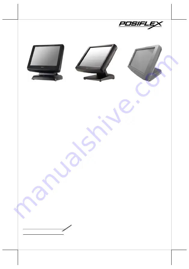
15” KS-7415/7415IR or 17” KS-7417/7417IR fanless touch terminal with  
Gen 5/Gen 6/Gen 8.5 base stand  (x 1) 


Power adapter   (x 1) 


Power cord    (x 1) 


User manual   (x 1) 

Product Features 


15” or 17” Resistive or IR touch screen  


Spill-resistant design to prevent careless spill and provide easy cleaning for a 
wide range of applications 


Equipped with Intel Bay Trail-D Quad Core J1900 2.0GHz CPU and DDR3L 
memory 


Fanless design boasting quiet and anti-dust features 


Patent aluminum die casting design for efficient cooling 


Optional UPS (Embedded on board developed by Posiflex)support to avoid 
sudden power loss 


Patent finger lever “Gear Lock” to adjust the terminal tilt angle from 15° to 70° 


Push-open cover to protect power switch from accidental shutdown 


Bottom cable guide design and cover for safety and neat outlook 


User-friendly mechanism for system upgrade and easy maintenance 


16390900010 Ver.Original


http://www.posiflex.com


KS-7415/7415IR/7417/7417IR 

     Fanless Touch Terminal 

     User Manual 

Summary of Contents for KS-7415

Page 1: ...and DDR3L memory Fanless design boasting quiet and anti dust features Patent aluminum die casting design for efficient cooling Optional UPS Embedded on board developed by Posiflex support to avoid sudden power loss Patent finger lever Gear Lock to adjust the terminal tilt angle from 15 to 70 Push open cover to protect power switch from accidental shutdown Bottom cable guide design and cover for sa...

Page 2: ...Base Stand Front View Rear View Side View Tilt Adjustment Lever Cable Cover Release Button Cable Exit HDD Cover Power Button Brightness Adjustment Button Brightness Adjustment Button USB Ports Resistive or IR Touch Panel Gen 5 Base Stand LED indicator ...

Page 3: ...ith Gen 6 Base Stand Front View Rear View Release Button Cable Passage Cable Holder Rubber Feet with Fixing Screw Rubber Feet with Fixing Screw Cable Groove Base Stand Cover Cable Exit HDD Cover Gen 6 Base Stand LED indicator Resistive or IR Touch Panel ...

Page 4: ...8 5 Base Stand Front View Rubber Feet with Fixing Screw Rubber Feet with Fixing Screw UPS Battery Compartment UPS Battery Bracket Power Button Brightness Adjustment Button Brightness Adjustment Button USB Ports Resistive or IR Touch Panel Gen 8 5 Base Stand LED indicator ...

Page 5: ...Cover Base Stand Cover UPS Battery Compartment Rubber Feet with Fixing Screw Rubber Feet with Fixing Screw Cable Exit HDD Cover Power adapter Compartment Power Button Brightness Adjustment Button Brightness Adjustment Button USB Ports PoweredUSB Compartment ...

Page 6: ...ion 1 Lay the terminal on a flat surface with its bottom I O plate facing you 2 Hold the base stand steady with its rear facing towards you 3 Attach four rail slots of the base stand to four locking bolts on the rear of the panel 4 Slide the base stand upwards along the rail slot until the terminal is clicked into place UPS Battery Connector DC In Jack CR Port LAN Ports VGA Port DB9 COM Ports RJ50...

Page 7: ...ic base stand connected to the POS system Please be careful not to touch the screen while setting up the tilt angle The terminal with Gen 5 Base Follow the below steps to adjust the viewing angle for the terminal with Gen 5 base using the tilt adjustment lever While pushing down the tilt adjustment lever on the right side of the stand tilt the screen up or back to your desired angle Then release t...

Page 8: ...the terminal in either low profile mode or full extended mode according to your situation Flat folded mode Low profile mode Full extended mode Below offer some instructions on how to switch among different positioning modes to find an ideal viewing angle for the terminal with Gen 8 5 base stand 1 Unpack KS 7415 7415IR 7417 7417IR which is supposed to be set in flat folded mode out of the package b...

Page 9: ... to your desired angle Please do not press on the screen while setting up the tilt angle 5 Position the terminal in Low Profile mode 5 1 First remove the cable cover Then support the screen with one hand holding onto its bottom edge While pulling the lever backwards move the display upwards or downwards until the lever is snapped into the upper hook as the below figure shows 5 2 Push the cable cov...

Page 10: ...ng Cables Each base stand features its own cable management to help you well organize the cords whenever you need to connect peripheral devices to the terminal Based on different base stands the following provides some useful cable routing instructions required to manage your cables For Gen 5 Base Stand 1 Make sure the terminal is released from Gen 5 base stand Then laying Gen5 base stand with its...

Page 11: ...om I O plate of your terminal For Gen 6 Base Stand 1 Tilt the display all the way down 2 To remove the base stand cover at the rear of the terminal pull the four locking levers outwards with your fingers and slide the cover in the direction shown by the arrow 3 Press down the cable tie tab to completely loosen the cable tie 4 Tighten the cable tie again to hold the cables into place Cable passage ...

Page 12: ... cable is threaded out of the cable exit put the base stand cover back into place For Gen 8 5 Base Stand 1 Title your display all the way down 2 Remove the cable cover at the rear of the terminal 3 Remove the base stand cover by pulling outwards the locking levers with your forefingers and then pulling the cover in the direction shown by the arrow Cable Exit Cable exit ...

Page 13: ...itionally installing multiple peripheral devices such as magnetic stripe reader MSR LCD monitor and cash drawer according to your preference The following will give you installation instructions on how to expand on your current POS system with these optional upgrade kits Before proceeding with the installation of peripherals please make sure the POS system is completely shut down to prevent damage...

Page 14: ... bracket to the wedged portions on the right hand side of the power adapter compartment 4 Fasten the bracket using two screws 5 Loosen two fixing screws to remove the bracket for middle compartment 6 Pass the cable of the power adapter through the cable exit and then connect it to the port on the I O plate of your POS system Please refer to Routing and Arranging Cables section to thread the cable ...

Page 15: ...ower adapter and the other end to the electrical outlet 10 To hold the power cord into place attach the screw hole of power adapter holder to the hole at the bottom of Gen 8 5 base stand and then use a fixing screw to secure the bracket For 120W 150W Power adapter 1 Lay your POS terminal on a flat surface with its screen facing downwards 2 Take the AC power adapter with its rubber feet facing you ...

Page 16: ...cable exit and then connect it to the port on the I O plate of your POS system Please refer to Routing and Arranging Cables section to thread the cable 7 Neatly thread the cord along the edge of the middle compartment 1 and then use the cable tie to hold the extra cable 2 as shown in the figure 8 Secure the middle compartment bracket using two fixing screws 9 Lay the POS terminal on a flat surface...

Page 17: ...e stand are slightly different Please follow the steps described below to finish the installation of UPS battery For Gen 5 Base Stand 1 Make sure the terminal is released from Gen 5 base stand After laying Gen 5 base stand with its bottom facing towards you completely loosen the four fixing screws to remove the bottom plate from the base stand 2 Well place UPS battery in the position as shown in t...

Page 18: ...ent is mainly used for installation of side mounted equipment such as magnetic stripe reader For detailed installation instructions please refer to the user manual specific to the device which you intend to mount Installing Rear Top Mount Upgrade Kits Rear top mount upgrade kits including customer pole displays and monitors have to be mounted onto the top side on the rear of your POS terminal as s...

Page 19: ...ow Installing an Operating System You are highly advised not to install an operating system on KS 7415 7415IR 7417 7417IR without professional instructions Not only might the careless handling during installation cause irreversible damage to your machine but also the improper installation likely leads to system malfunction or failure Please contact with your dealers about the issues of operating s...

Page 20: ...e Touch KS 7415 7417 Serial Port 4 ports DB9 x 3 RJ50 x 1 5V 12V support on all COM ports Parallel Port 1 via optional conversion cable Standard USB Port USB 2 0 x 6 LAN Port 10 100 1000 Mb x 1 VGA Port VGA x 1 12V support for Posiflex monitors CR Port 1 controlling 2 CR via optional Y cable UPS Port Yes for optional UPS battery HDMI Port 1 PS 2 Port Pin header inside service window Audio Internal...

Reviews: