background image


Operating instructions 
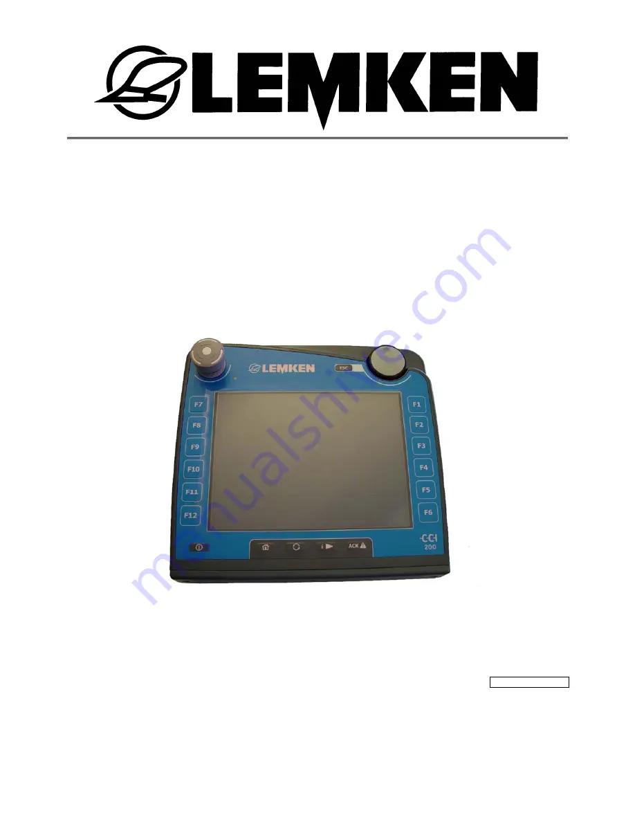
Control terminal 

CCI-ISOBUS 


- EN - 


Art. no.175_4729

            1/07.10   

LEMKEN GmbH & Co. KG 

Weseler Strasse 5, D-46519 Alpen / P.O. Box 11 60, D-46515, Germany Alpen 

Phone +49 (0) 28 02 81-0, Fax +49 (0) 28 02 81-220 

Email: [email protected], Internet: http://www.lemken.com 

Summary of Contents for CCI-ISOBUS

Page 1: ...l terminal CCI ISOBUS EN Art no 175_4729 1 07 10 LEMKEN GmbH Co KG Weseler Strasse 5 D 46519 Alpen P O Box 11 60 D 46515 Germany Alpen Phone 49 0 28 02 81 0 Fax 49 0 28 02 81 220 Email lemken lemken com Internet http www lemken com ...

Page 2: ...he options available for using it The operating instructions contain important information about how to operate the device safely properly and efficiently Following the instructions will help to pre vent hazards faults and down times and will increase reliability and service life Read the operating instructions carefully and attentively before commissioning Make sure that the operating instruction...

Page 3: ... state the type designation and serial number of the device This information can be found on the rating plate Enter this data in the fields below so that it is always within easy reach Type designation Serial number Remember that you should only use genuine LEMKEN spare parts Reproduction parts have a negative influence on the function of the device have a shorter ser vice life and present risks a...

Page 4: ...allation of electrical and electronic devices and or components 8 2 4 Safety instruction for Function Stop switch 10 3 Commissioning 11 3 1 Installation in the cab 11 3 2 Connector in agricultural tractor 11 3 2 1 ISOBUS connector 11 3 2 2 Signal socket 11 3 3 Terminal connector 13 3 4 Pin assignment 14 3 5 Connecting the terminal 15 3 6 Switching on the terminal 17 4 Keypad and screen 18 4 1 Cont...

Page 5: ...th the slide control 23 5 2 Input dialog box for boolean values 24 5 3 Input dialog box for list selection 25 6 Menu structure 26 6 1 Graphical overview 26 6 2 Main menu 27 6 2 1 Start menu 27 6 2 2 System settings 28 6 2 3 Country settings 31 6 2 4 Information Diagnosis 33 6 2 5 Service 36 7 Technical data 37 7 1 Mechanical values 37 7 2 Electronics 37 7 3 CCI 100 interfaces 37 CCI 200 interfaces...

Page 6: ...ruction for step 2 Instructions that contain only one single step are not numbered The same applies to instructional steps in which the sequence in which they are to be performed is not specified One point has been placed ahead of these instructions Instruction 1 2 2 Meaning of warning signs CAUTION Type of danger This information warns of a situation that may be hazardous to a person s health or ...

Page 7: ...nded use The manufacturer shall not be held liable for any resulting damage to persons or material The user shall bear all risks associated with improper usage Use in accordance with designated purpose also includes adherence to the manu facturer s specified operating and repair conditions The pertinent accident prevention regulations as well as any generally approved safety related industrial med...

Page 8: ...in the manual and the safety labels attached to the device Safety labels must always be in a clearly legible condition Replace any missing or damaged labels Make sure that the device parts have the latest safety labels affixed to them Replacement labels are available from your local authorised dealer Familiarise yourself with the terminal to enable you to operate it properly Ensure that the termin...

Page 9: ...th the valid national regulations e g registration with German Fed eral Agency for Telecommunication Registrations BZT may be installed The device must be permanently installed The operation of portable or mobile devices within the vehicle is only permissible if there is a permanently installed outer aerial The transmitting part is to be installed separate to the vehicle electronics The aerial mus...

Page 10: ...unction Stop switch never intervenes in any tractor functions i e neither the cardan shafts nor the hydraulic function are impaired More information on this is available in your machine s operating instructions Figure 1 Function Stop CAUTION Check support for Function Stop At this moment in time not all ISOBUS machines support this function Please consult the operating instructions for the trailer...

Page 11: ... connector ISO 11783 The power supply to the terminals is also connected through this connector 1 4 7 3 6 9 Figure 2 View and pin assignment for ISOBUS connector 3 2 2 Signal socket The pulses for the current speed are sent over the 7 pin connector DIN 9684 1 ISO 11786 to the terminal These are required if the TECU software tractor ECU which is part of the terminal delivery package is to be used T...

Page 12: ...Commissioning 12 Figure 3 Pin assignment for signal socket ...

Page 13: ...cated on the rear of the terminal In addition to the dis played interfaces you will find the USB connection behind a flap on the rear of terminal Designation 1 CAN1 IN 2 CAN1 OUT 3 CAN2 IN 4 Video IN 5 SIGNAL ISO 11786 6 RS232 1 7 RS232 2 8 WLAN 9 LIN OUT 10 ETHERNET 6 5 4 3 2 1 9 1 7 8 ...

Page 14: ...ck Supply ground SIGNAL M12x1 5 pin socket 1 Cut in signal Brown Supply UB switched 2 FQ2 White ISO11786 Rear PTO rotational speed 3 GND Blue Supply ground 4 FQ1 Black ISO11786 True ground speed 5 5 Analogue input Green yell ow ISO11786 Linkage position CAN1 OUT M12 x1 8 pin socket ISOBUS 1 12V 24V White Supply UB 2 Emergency Stop B Brown Hardware Emergency Stop output 3 Cut in signal Green Cut in...

Page 15: ... 3 8 Screen Red Screen capacitively decoupled 8 WLAN aerial SMA socket only available for connectors with strands 3 5 Connecting the terminal For connection to the ISOBUS a special cable set is required which can be or dered by quoting the LEMKEN article number 573 6204 Perform the steps in the following sequence Choose a suitable position in the tractor cab in driver s field of vision where you w...

Page 16: ...Commissioning 16 Figure 5 Schematic connection overview ...

Page 17: ...ching on the terminal for the first time check the connections are cor rectly and securely fitted to the device The terminal is switched on using the ON OFF key at the bottom left of the hous ing see Figure 6 Please press and hold the key for roughly 2 seconds ...

Page 18: ...ease consult the operating instructions for the trailer device 4 1 2 WorkingSet key Repeatedly pressing this key enables a sequential change to be made between currently active applica tions e g from machine operation to the TECU etc INFORMATION When changing from an active machine function functions that are running may be automatically shut down on some machines Please consult the operating inst...

Page 19: ... Touch screen For menu navigation and comfortable entry of values and text the operating unit has been equipped with a premium quality touch screen which enables functions to be called up or values entered straight away on the screen 4 1 6 Scroll wheel The scroll wheel is used for immediate fast entry of specified values as well as for navigation through list elements Turning the scroll wheel to t...

Page 20: ... display are six soft keys F1 F12 Pressing a soft key executes the function immediately next to the key in the display A key mounted on the rear enables the assignment of the soft keys to be changed from the left to the rear side or from the right to the left side This in turn means that the device can be operated with one handt 4 1 9 Creating a screen shot A picture often says more than a thousan...

Page 21: ...used to cancel any actions in all the input dialog boxes i e the previ ous value is then retained Alternatively the action can also be cancelled using the ESC key on the keypad 5 1 Input dialog box for numerical values If a numerical value is selected in a control screen then this input dialog box ap pears There are 3 display forms for the input dialog box for numerical values which by pressing th...

Page 22: ...numerical values using the numerical keypad Enter the new value directly using the keypad or change the value by turning the scroll wheel 5 1 2 Scroll wheel Figure 8 Entering numerical values using the scroll wheel Change the value by turning the scroll wheel ...

Page 23: ...dly pressing the or buttons or change the value by turning the scroll wheel INFORMATION The terminal remembers the last display form used The next time the input dialog box is called up for numerical values this is then immediately chosen as the display form INFORMATION If a value is entered that is outside the valid value range then the input field is highlighted in red Please change the value ac...

Page 24: ...lean value 1 Choose the value to be changed in the control screen To do so simply press the value in the touch screen or turn the scroll wheel until the value turns white and then push the scroll wheel 2 The input dialog box is opened 3 Change the value by pressing or you can change the value by pressing the scroll wheel 4 You can exit the input dialog box by pressing either OK or ESC Figure 10 In...

Page 25: ...To do so simply press the value in the touch screen or turn the scroll wheel until the value turns white and then push the scroll wheel 2 The list selection input dialog box is opened 3 Select the new value from the list by turning the scroll wheel or Pull the scroll bar on the right side of the list up or down until the required list value is reached Select the desired entry by pressing on the to...

Page 26: ...tings are made in the menu tree which can be accessed through the main menu For a better overview the available menu items are shows as follows in a tree form The various settings are looked at in more detail in the following chapters 6 1 Graphical overview ...

Page 27: ...ttings Information Diagnosis Service settings 6 2 1 Start menu All the active applications can be accessed from the Start menu This includes the applications installed on the application e g tractor ECU and the operating images for the connected ISOBUS machines After selecting the required application it is then activated i e shown on the screen ...

Page 28: ...s 6 2 2 1 1 Display lighting Day Set the display brightness level for working through the day The value can be adjusted in a range from 0 100 with an increment of 10 Changes take effect after exiting the input dialog box 6 2 2 1 2 Display lighting Night Set the display brightness level for working through the night The value can be adjusted in a range from 0 100 with an increment of 10 Changes tak...

Page 29: ...the control screen 6 2 2 2 2 Volume Set the required volume for the signal generator The value can be adjusted in a range from 30 100 6 2 2 2 3 Touch screen calibration Calibrate the touch screen by selecting the five crosses shown on the screen in succession as close to the centre as possible To complete the calibration process and to accept the determined values touch a point of your own choosin...

Page 30: ...settings menu item can be used to configure the physical inter faces At the time of printing this document only the Ethernet interface can be con figured 6 2 2 4 1 LAN INFORMATION The settings described below are only of any interest when the terminal is operated in a network and therefore they normally do not need to be made Consult your network administrator to make the settings Enter the correc...

Page 31: ...his printed version currently supports the following languages German English French Hungarian Software updates enable this selection to be extended if required In cases of doubt you can open the selection list by pressing the Language but ton all installed languages are then displayed Now you can choose the required language 6 2 3 2Unit system The terminal supports the following unit systems Metr...

Page 32: ...the terminal to the ISOBUS 6 2 3 4Time format Set whether the time is to be managed and displayed in 24h format in other words from 0 23 hours or in 12h format i e 1 12 a m p m 12h 24h INFORMATION This setting only affects the time information transferred from the terminal to the ISOBUS 6 2 3 5Number format Select the required method of displaying the decimal point or ...

Page 33: ...basic information on the devices connected to the ISOBUS INFORMATION This menu is used for information on both the test and the hardware 6 2 4 1Version data Change from the Information and diagnosis menu into the submenu called Version data The following information is then shown in the display Terminal firmware version ANEDO System Operating system Version of all software plug ins Acknowledge the...

Page 34: ... and diagnosis menu into the submenu called Memory status The following information is then shown in the display for the main memory RAM and the memory Flash Total available memory capacity used memory capacity and free memory space Acknowledge the message with OK and return to the menu 6 2 4 4Function Stop status Change from the Information and diagnosis menu into the submenu called Function Stop...

Page 35: ...the correct functionality of the following keys on the control panel F1 F12 ESC Scroll wheel ACK Backspace key 6 2 4 6 2 Display test A coloured circle is shown Use the arrow key F7 to return to the menu 6 2 4 6 3 Touch test Five empty check boxes are shown on the display A tick should be set in each individual button Return to the menu using the arrow key F7 6 2 4 6 4 Light sensor test Cover up t...

Page 36: ...ucture 36 6 2 5 Service The Service menu item is protected by a password known to the manufacturer or the sales and service partner only Access to this menu and its submenus is re stricted to Service staff only ...

Page 37: ...ion px 640 x 480 7 3 CCI 100 interfaces CAN1 IN CAN 2 0B ISO 11898 1 M 12x1 8 pin plug CAN1 OUT CAN 2 0B ISO 11898 1 M 12x1 8 pin socket LIN OUT LIN BUS Master M 8x1 4 pin socket RS232 1 Asynchronous to 115 Kbps M 8x1 4 pin plug RS232 2 Asynchronous to 115 Kbps M 8x1 4 pin plug Signal Signal socket ISO 11786 M 12x1 5 pin socket Video NTSC SECAM signal 1 Vpp 50 USB USB Host 2 0 CCI 200 interfaces A...

Page 38: ...nction Stop 10 Figure 2 View and pin assignment for ISOBUS connector 11 Figure 3 Pin assignment for signal socket 12 Figure 4 Interface bar 13 Figure 5 Schematic connection overview 16 Figure 6 Keypad and screen 18 Figure 7 Entering numerical values using the numerical keypad 22 Figure 8 Entering numerical values using the scroll wheel 22 Figure 9 Entering numerical values using the slide control ...

Reviews: