background image

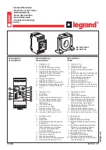
PNOZ XV2.1

Operating Manual-20690-EN-08

}

Safety relays

Summary of Contents for PNOZ XV2

Page 1: ...PNOZ XV2 1 Operating Manual 20690 EN 08 Safety relays...

Page 2: ...nta tion will be gratefully received Source code from third party manufacturers or open source software has been used for some components The relevant licence information is available on the Internet...

Page 3: ...d liability 6 Disposal 6 For your safety 6 Unit features 7 Safety features 7 Block diagram terminal configuration 7 Function Description 8 Operating modes 8 Timing diagram 9 Installation 9 Wiring 10 P...

Page 4: ...larly important is identified as follows DANGER This warning must be heeded It warns of a hazardous situation that poses an immediate threat of serious injury and death and indicates preventive measur...

Page 5: ...ICE EMC compliant electrical installation The product is designed for use in an industrial environment The product may cause interference if installed in other environments If installed in other envir...

Page 6: ...wledge of the generic and specialist standards applicable to the specific application Warranty and liability All claims to warranty and liability will be rendered invalid if The product was used contr...

Page 7: ...able Possible to cancel delay time See order reference for unit types Safety features The safety relay meets the following safety requirements The circuit is redundant with built in self monitoring Th...

Page 8: ...n be ready for operation Set delay time On units with selectable delay time the delay time of the safety contacts 37 38 and 47 48 can be set on the front of the unit using a screwdriver Reset function...

Page 9: ...elay t2 Delay on de energisation t3 Waiting period with a monitored start t4 Recovery time tv Delay time NOTICE At the latest the delay on de energisation safety contacts open after the set delay time...

Page 10: ...the separate routing of cables of the control circuits input start and feedback loop from other cables for energy trans mission or the shielding of cables for example Adequate protection must be prov...

Page 11: ...cross contacts S1 S22 S21 S12 S32 S11 S31 E STOP with detection of shorts across contacts S1 S22 S31 S32 S21 S12 S11 Safety gate without detection of shorts across contacts S1 S22 S21 S12 S32 S11 S31...

Page 12: ...OTICE With automatic start The unit starts up automatically when the safeguard is reset e g when the E STOP pushbutton is released Use external circuit measures to prevent an unexpected restart Reset...

Page 13: ...tacts on the relay outputs open correctly Open the safety contacts switch off output and start the device again so that the internal diagnostics can check that the safety contacts open correctly for S...

Page 14: ...oltage is switched off for approx 1 minute the unit is ready for operation again Contact malfunctions If the contacts have welded reactivation will not be possible after the input circuit has opened L...

Page 15: ...cycle 100 100 100 Inputs 774550 774552 774558 Number 2 2 2 Voltage at Input circuit DC 24 V 24 V 24 V Start circuit DC 24 V 24 V 24 V Feedback loop DC 24 V 24 V 24 V Current at Input circuit DC 35 mA...

Page 16: ...0 01 A 0 01 A Max current 8 A 8 A 8 A Max power 2000 VA 2000 VA 2000 VA DC1 at 24 V 24 V 24 V Min current 0 01 A 0 01 A 0 01 A Max current 8 A 8 A 8 A Max power 200 W 200 W 200 W Utilisation category...

Page 17: ...0 A Blow out fuse slow 6 A 6 A 6 A Blow out fuse gG 10 A 10 A 10 A Circuit breaker 24 V AC DC characteristic B C 6 A 6 A 6 A Contact material AgSnO2 0 2 m Au AgSnO2 0 2 m Au AgSnO2 0 2 m Au Convention...

Page 18: ...ms 170 ms Recovery time at max switching frequency 1 s After E STOP 50 ms tv 50 ms tv 50 ms tv After power failure on wide range power sup ply 1500 ms 1500 ms 1500 ms Delay time tv 0 1 s 0 5 s 1 s 2 s...

Page 19: ...4 kV 4 kV Protection type Housing IP40 IP40 IP40 Terminals IP20 IP20 IP20 Mounting area e g control cabinet IP54 IP54 IP54 Mechanical data 774550 774552 774558 Mounting position Any Any Any Mechanical...

Page 20: ...20 Safety contacts delayed 30 s PL d Cat 3 SIL CL 3 2 64E 09 20 Safety contacts delayed 30 s PL c Cat 1 SIL CL 1 2 87E 09 20 Explanatory notes for the safety related characteristic data The SIL CL va...

Page 21: ...data is only valid if the values in the service life graphs are met The PFH value depends on the switch frequency and the load of the relay output If the service life graphs are not accessible the st...

Page 22: ...Switching current A Example Inductive load 0 2 A Utilisation category AC15 Contact service life 4 000 000 cycles Provided the application to be implemented requires fewer than 4 000 000 cycles the PFH...

Page 23: ...inals 774550 PNOZ XV2 1 24 240 V AC DC Delay up to 300 s selectable Screw terminals 774558 EC declaration of conformity This product these products meet the requirements of the directive 2006 42 EC fo...

Page 24: ...g energy efficient products and environmentally friendly solutions We are represented internationally Please refer to our homepage www pilz com for further details or contact our headquarters Headquar...

Reviews: