background image


IDS-409C Switches 

Quick Start Guide 

___________________________________________________ 

This guide covers basic installation and configuration and is intended for first time 
setup or product evaluation.  

Complete details can be found in the following guides a

www.perle.com/downloads

. 


IDS-409C Hardware Installation Guide 


IDS Managed Switches User Guide 


IDS Managed Switches CLI Guide 
 

What’s in the box? 


The IDS switch 


Quick Start Guide (this document) 
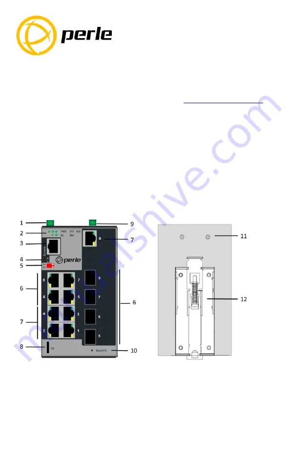
 

Hardware Overview


         Front View  

                          Back View 


1 – Terminal Block for Power 1, 2 

7 – Ethernet Ports 


2 – Status LEDs 

8 – SD card slot 

3 – Console Port – serial 

9 – Terminal Block – Relay, I/O 

4 – Console Port – USB 


10 – Reset / FS (Fast Setup) 

5 – DIP switches 

11 – Wall Mount Bracket Screw Holes 

6 – Combo Ports - Ethernet/SFP* 


12 – DIN Rail Clip 


*


Combo ports share a common status LED located on the Ethernet connector.


Summary of Contents for IDS-409C

Page 1: ...tion Guide IDS Managed Switches User Guide IDS Managed Switches CLI Guide What s in the box The IDS switch Quick Start Guide this document Hardware Overview Front View Back View 1 Terminal Block for Power 1 2 7 Ethernet Ports 2 Status LEDs 8 SD card slot 3 Console Port serial 9 Terminal Block Relay I O 4 Console Port USB 10 Reset FS Fast Setup 5 DIP switches 11 Wall Mount Bracket Screw Holes 6 Com...

Page 2: ...connector if removed Turn power on at source Check LED indicators for status 6 Connect P2 power source 2 beginning at Step 1 For complete wiring instructions and for all Hazardous Locations and general safety warnings consult the Hardware Installation Guide Inserting a SFP Module Before connecting fiber cable to the switch the SFP s must be installed following the procedure below 1 Carefully align...

Page 3: ...cations Red Neither P1 or P2 providing power within specifications SYS System status Green blinking System booting Green solid System operating normally Green blinking fast Fast Setup mode activated Red Hardware fault or firmware load error Ethernet Port Link Speed Green and Yellow LEDs 1000 Mbps Green on Yellow off 100 Mbps Green on Yellow on 10 Mbps Green off Yellow on Note Blinking indicates ac...

Page 4: ... recessed in the switch a small tool such as a paper clip will be required The yellow and green LEDs on an unused RJ 45 connector will flash rapidly to indicate where to plug in the Ethernet cable from your PC 3 Using a web browser enter to a well known webpage such as www google com you will be automatically directed to the IDS Get Started screen Note While in Fast setup mode the IDS switch will ...

Reviews: