background image

TQB2AA0547

Operating Instructions

Manual de instrucciones

High Definition Plasma Display

Alta definición Pantalla de plasma 

Model No.

Número de modelo

TH-42PD12U
TH-50PD12U

English

Español

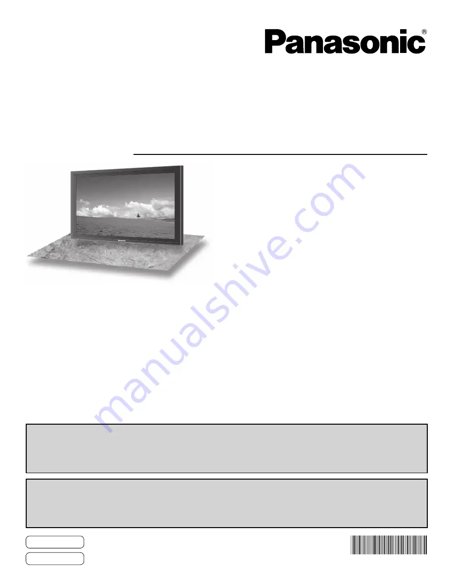
The illustration shown is an image.
Before connecting, operating or adjusting this product, please read these instructions completely.
Please keep this manual for future reference.

La ilustración mostrada es una imagen.
Antes de conectar, utilizar o ajustar este producto, lea completamente este manual de instrucciones;
y guárdelo para consultarlo en el futuro en caso de ser necesario.

For more detailed instructions, refer to the Operating Instructions on the CD-ROM.
To view the Operating Instructions on the CD-ROM, you need a computer equipped with a CD-ROM drive, and 
Adobe

®

 Reader

®

 (Version 7.0 or later is recommended) installed on your computer.

Depending on the operating system or settings on your computer, the Operating Instructions may not start automatically.
In this case, open the PDF file under \MANUAL\PDF manually to view the instructions.

Para obtener instrucciones más detalladas, consulte las instrucciones de manejo contenidas en el CD-ROM.
Para ver las instrucciones de manejo contenidas en el CD-ROM, se necesita un ordenador equipado con una
unidad de CD-ROM, y que tenga instalado Adobe

®

 Reader

®

 (se recomienda la versión 7.0 o posterior).

Dependiendo del sistema operativo o de las configuraciones del ordenador, las instrucciones de manejo pueden no iniciarse automáticamente.
En tal caso, abra manualmente el archivo PDF en \MANUAL\PDF para visualizar las instrucciones.

Contents

Important Safety Instructions  ···········································  3
FCC STATEMENT  ·······························································  4
Safety Precautions  ····························································  5
Maintenance  ·······································································  6
Accessories  ·······································································  7
Connections  ·······································································  8
Power ON / OFF  ·······························································  12

Selecting the input signal  ···············································  14
Basic Controls  ·································································  15
On-Screen Menu Displays  ··············································  17
Specifications  ··································································  18
Panasonic Professional Flat Panel Display Limited Warranty  ··  19
LIMITED WARRANTY STATEMENT  ································  20
Customer Service  ····························································  21

Summary of Contents for TQB2AA0547

Page 1: ...ating system or settings on your computer the Operating Instructions may not start automatically In this case open the PDF file under MANUAL PDF manually to view the instructions Para obtener instrucciones más detalladas consulte las instrucciones de manejo contenidas en el CD ROM Para ver las instrucciones de manejo contenidas en el CD ROM se necesita un ordenador equipado con una unidad de CD RO...

Page 2: ...DO NOT OPEN WARNING To prevent damage which may result in fire or shock hazard do not expose this apparatus to rain or moisture Do not place containers with water flower vase cups cosmetics etc above the set including on shelves above etc WARNING 1 To prevent electric shock do not remove cover No user serviceable parts inside Refer servicing to qualified service personnel 2 Do not remove the groun...

Page 3: ...ent of the obsolete outlet 10 Protect the power cord from being walked on or pinched particularly at plugs convenience receptacles and the point where they exit from the apparatus 11 Only use attachments accessories specified by the manufacturer 12 Use only with the cart stand tripod bracket or table specified by the manufacturer or sold with the apparatus When a cart is used use caution when movi...

Page 4: ...d 2 this device must accept any interference received including interference that may cause undesired operation FCC CAUTION To assure continued compliance follow the attached installation instructions and use only shielded interface cables when connecting to computer or peripheral devices Any changes or modifications not expressly approved by Panasonic Corp of North America could void the user s a...

Page 5: ... the power cord plug can increase humidity which might damage the insulation and cause fire Unplug the cord from the wall outlet and clean it with a dry cloth This Plasma Display radiates infrared rays therefore it may affect other infrared communication equipment Install your infrared sensor in a place away from direct or reflected light from your Plasma Display Note Do not allow a still picture ...

Page 6: ...estal optional accessory leave a space of 3 15 16 10 cm or more at the top left and right and 2 3 4 7 cm or more at the rear and also keep the space between the bottom of the display and the floor surface If using some other setting up method follow the manual of it If there is no specific indication of installation dimension in the installation manual leave a space of 3 15 16 10 cm or more at the...

Page 7: ...harge short circuit disassemble heat or burn used batteries 5 Battery replacement is necessary when the remote control acts sporadically or stops operating the Plasma Display 6 Do not burn or breakup batteries Batteries must not be exposed to excessive heat such as sunshine fire or the like 3 Replace the cover Accessories Supplied Check that you have the Accessories and items shown Operating Instr...

Page 8: ... cable fixing band through the clip as shown in the figure To secure cables connected to Terminals wrap the cable fixing band around them then pass the pointed end through the locking block as shown in the figure While ensuring there is sufficient slack in cables to minimize stress especially in the power cord firmly bind all cables with the supplied fixing band To tighten To loosen Pull Pull Push...

Page 9: ... computers with DOS V compatible Mini D sub 15P terminal The computer shown in the illustration is for example purposes only Additional equipment and cables shown are not supplied with this set Do not set the horizontal and vertical scanning frequencies for PC signals which are above or below the specified frequency range Component Input is possible with the pin 1 2 3 of the Mini D sub 15P Connect...

Page 10: ...Parameter s 1 5 bytes End 03h STX C1 C2 C3 P1 P2 P3 P4 P5 ETX Notes If multiple commands are transmitted be sure to wait for the response for the first command to come from this unit before sending the next command If an incorrect command is sent by mistake this unit will send an ER401 command back to the computer Pin layout for SERIAL Terminal COMPUTER RS 232C Straight cable D sub 9p Command Para...

Page 11: ...ONENT RGB IN SELECT setting in the SET UP menu to COMPONENT when COMPONENT signal connection or RGB when RGB signal connection SYNC ON G signal is needed VIDEO OUT AUDIO OUT RGBOUT YPB PR OUT L R AUDIO OUT L R S VIDEO OUT AUDIO OUT L R A B A B VCR RCA BNC adapter plug DVD player DVD player Computer RGB Camcorder RCA BNC adapter plug ...

Page 12: ...socket outlet first Press the Power switch on the Plasma Display to turn the set on Power On Power Indicator Green Press the button on the remote control to turn the Plasma Display off Power Indicator Red standby Press the button on the remote control to turn the Plasma Display on Power Indicator Green Turn the power to the Plasma Display off by pressing the switch on the unit when the Plasma Disp...

Page 13: ... unit Following screen will be displayed when the unit is turned on for the first time Select the items with the remote control Unit buttons are invalid OSD LANGUAGE DISPLAY ORIENTATION 1 Select the language 2 Set 1 For vertical installation select PORTRAIT 2 Set Notes Once the items are set the screens won t be displayed when switching on the unit next time After the setting the items can be chan...

Page 14: ...d to the component RGB input terminals In 2 screen display the same input mode cannot be selected for the main picture and sub picture Image retention image lag may occur on the plasma display panel when a still picture is kept on the panel for an extended period The function that darkens the screen slightly is activated to prevent image retention but this function is not the perfect solution to i...

Page 15: ...er OFF Indicator not illuminated The unit will still consume some power as long as the power cord is still inserted into the wall outlet Standby Red Power ON Green DPMS POWER MANAGEMENT Orange With PC input signal Volume Adjustment Volume Up Down When the menu screen is displayed press to move the cursor up press to move the cursor down see page 17 Enter Aspect button see page 17 Normal Viewing PI...

Page 16: ... Zoom Remote Control Transmitter AUTO SETUP button Automatically adjusts the position size of the screen SET UP button SOUND button Volume Adjustment Press the Volume Up or Down button to increase or decrease the sound volume level R button see page 17 Press the R button to return to previous menu screen OFF TIMER button The Plasma Display can be preset to switch to stand by after a fixed period T...

Page 17: ...NSION AGC GAMMA INPUT LEVEL ADVANCED SETTINGS NORMAL NORMALIZE OFF 0 0 0 SOUND NORMAL NORMALIZE STANDARD TREBLE AUDIO MENU BALANCE BASS MAIN AUDIO OUT PIP EXPRESS SETTINGS CUSTOM SETTINGS RESET EXTENDED LIFE SETTINGS 17 On Screen Menu Displays Remote Control Unit 1 Display the menu screen Press to select Example PICTURE menu MENU Press several times Each time the MENU button is pressed the menu sc...

Page 18: ...XGA SXGA UXGA compressed Horizontal scanning frequency 15 110 kHz Vertical scanning frequency 48 120 Hz Connection terminals VIDEO BNC 1 0 Vp p 75 Ω S VIDEO MINI DIN 4PIN Y 1 0 Vp p 75 Ω C 0 286 Vp p 75 Ω COMPONENT RGB Y G BNC PB B BNC PR R BNC with sync 1 0 Vp p 75 Ω 0 7 Vp p 75 Ω PC HIGH DENSITY MINI D SUB 15PIN B PB CB R PR CR HD VD Y or G with sync 1 0 Vp p 75 Ω Y or G without sync 0 7 Vp p 75...

Page 19: ...s indicated above Panasonic Professional Display Company referred to as the Warrantor will repair this product and all included accessories with new or refurbished parts free of charge in the USA or Puerto Rico of the original purchase in the event of a defect in materials or workmanship as follows In the USA and Puerto Rico FOR SERVICE CALL TOLL FREE 1 800 973 4390 2 Years 2 Years On site or carr...

Page 20: ...rage period Proof of product purchase is a condition of warranty service The owner must produce the product purchase receipt or other satisfactory evidence of date of original purchase This warranty does not apply to external appearance items such as handles knobs safety windows etc This warranty does not apply to any part or parts of the product installed altered repaired or misused in any way th...

Page 21: ...21 ...

Page 22: ...Note ...

Page 23: ...Note ...

Page 24: ... Panasonic Way 1F 10 Secaucus NJ 07094 EASTERN ZONE One Panasonic Way 4E 7 Secaucus NJ 07094 201 348 7621 Mid Atlantic New England One Panasonic Way 4E 7 Secaucus NJ 07094 201 348 7621 Southeast Region 1225 Northbrook Parkway Ste 1 160 Suwanee GA 30024 770 338 6835 Central Region 1707 N Randall Road E1 C 1 Elgin IL 60123 847 468 5200 WESTERN ZONE 3330 Cahuenga Blvd W Los Angeles CA 90068 323 436 3...

Reviews: