UPC-V315-QM77 Panel PC
Page i
Us e r Ma n u a l
UPC-V315-QM77 Panel PC
MODEL:
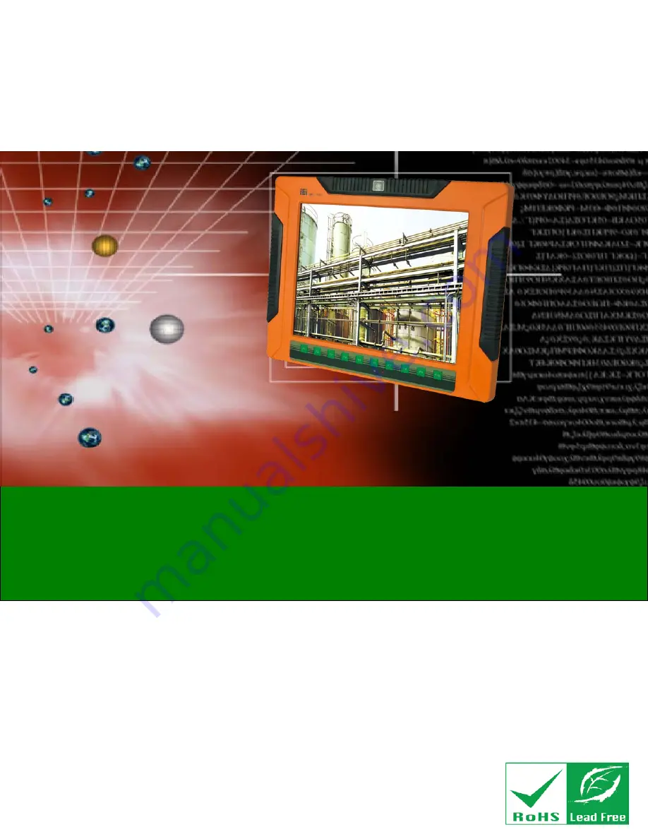
UP C-V315-QM77
P a n e l P C with To u c h S c re e n a n d In te l® Co re ™ i3-3217UE/
i7-3517UE P ro c e s s o r, Gb E, Wire le s s , US B, Au d io ,
RS -232/422/485, Ro HS Co m p lia n t, IP 65 P ro te c tio n
Re v. 1.01 – 9 Fe b ru a ry, 2015
Summary of Contents for UPC-V315-QM77
Page 12: ......
Page 13: ...UPC V315 QM77 Panel PC Page 1 1 Introduction Chapter 1 ...
Page 26: ...UPC V315 QM77 Panel PC Page 14 2 Unpacking Chapter 2 ...
Page 30: ...UPC V315 QM77 Panel PC Page 18 3 Ins tallation Chapter 3 ...
Page 60: ...UPC V315 QM77 Panel PC Page 48 4 BIOS Chapter 4 ...
Page 93: ...UPC V315 QM77 Panel PC Page 81 A BIOS Menu Options Appendix A ...
Page 96: ...UPC V315 QM77 Panel PC Page 84 Appendix B B One Key Recovery ...
Page 104: ...UPC V315 QM77 Panel PC Page 92 Figure B 5 Partition Creation Commands ...
Page 137: ...UPC V315 QM77 Panel PC Page 125 C Safety Precautions Appendix C ...
Page 142: ...UPC V315 QM77 Panel PC Page 130 D Hazardous Materials Dis clos ure Appendix E ...