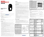
background image


I

I

N

N

S

S

T

T

A

A

L

L

L

L

A

A

T

T

I

I

O

O

N

N

,

,


O

O

P

P

E

E

R

R

A

A

T

T

I

I

N

N

G

G


A

A

N

N

D

D


M

M

A

A

I

I

N

N

T

T

E

E

N

N

A

A

N

N

C

C

E

E


M

M

A

A

N

N

U

U

A

A

L

L


Summary of Contents for Surveyor 4B

Page 1: ...I IN NS ST TA AL LL LA AT TI IO ON N O OP PE ER RA AT TI IN NG G A AN ND D M MA AI IN NT TE EN NA AN NC CE E M MA AN NU UA AL L...

Page 2: ......

Page 3: ...S AND DUST MONITORING We thank you for choosing an OLDHAM SA instrument We have taken every step to ensure that this equipment continues to give you complete satisfaction Please read the instruction m...

Page 4: ...ications and data included herein contain confidential information which is the property of OLDHAM SA These information shall not be in part or in whole physically electronically or in any other form...

Page 5: ...ly as concerns electricity and fitting connections and connection to the power network Any modification of the equipment or the use of parts not specified as original manufacturer s parts could lead t...

Page 6: ...mples of installation 10 3 5 Examples of installation 11 IV OPERATING INSTRUCTIONS 13 4 1 Switching on 13 4 2 Switching off 13 4 3 Alarms 13 4 3 1 GAS alarm 13 4 3 2 FAULT alarms 14 4 4 Adjustments 14...

Page 7: ...ests on the top item 1 indicator lights on the FRONT face item 2 connections at the bottom item 3 II MOUNTING OF THE SURVEYOR 4B The surveyor 4B appliance fitted on its symmetrical DIN rail can be ins...

Page 8: ...r 12 V 2 3 1 Alternative power supply 230 volt AC power supply The Surveyor 4B must be protected on the upstream side by a two pole earth leakage circuit breaker 1A The response curve must be of type...

Page 9: ...opposite mode see Fig 3 The maximum loop resistance is 1 4 ohms For example the maximum distance between Surveyor 4B and the detector will be 40 m with conductors with a cross section of 1 5 mm In so...

Page 10: ...s available on the S4B terminal block item 3 Fig 5 Relay 2 REL 2 which is negative safety mode corresponds to the second gas threshold only This relay is also equipped with SPDT contacts available on...

Page 11: ...ta at tu us s d di is sp pl la ay y l li ig gn nt t Gas valve closed Breaking capacity of rating relays switch contact 120VA ou 30W Important The relay s contacts are shown on the SV4B label unit swit...

Page 12: ...a al lv ve e s st ta at tu us s d di is sp pl la ay y l li ig gn nt t Gas valve closed Breaking capacity of rating relays switch contact 120VA ou 30W Important The relay s contacts are shown on the SV...

Page 13: ...ositive safety position 4 2 Switching off The S4B is switched off by cutting off the power supply on an electrical equipment cabinet 4 3 Alarms 4 3 1 GAS alarm The S4B has two adjustable GAS alarm thr...

Page 14: ...nd adjustments described in this chapter must be performed by authorized personnel only as they can affect the appliance s reliability in detection 4 4 1 Adjusting the gas alarm thresholds Using a ref...

Page 15: ...corresponding to a different gas content level For example when you inject 1 methane you read 1 000 mV for instance If you set the alarm potentiometer to read 1 500 mV the alarm is triggered at 1 5 me...

Page 16: ...m 1 4 4 3 Checking the sensitivity Necessary when a cell is replaced At least twice a year Prepare the calibration kit and secure the gas input pipe to the detector Adjust the flow rate of the referen...

Page 17: ...is satisfactory Cell sensitivity is inadequate Can AL 1 be triggered by adjusting the alarm potentiometer item 2 Fig 8 Cell sensitivity is now satisfactory Cell sensitivity is inadequate replace the...

Page 18: ...ise the reliability of the equipment could be adversely affected The fuse Fig 9 item 1 must be replaced by qualified personnel only The fuse is and must be in compliance with CEI 127 with time delay l...

Page 19: ...ection Fuse Relays Relay 1 Relay 2 Common to gas and fault Gas Contact SPDT relay 1 positive safety SPDT relay 2 Max breaking capacity 60 VA or 28 W resistive Maximum voltage 240 V or 60 V Maximum cur...

Page 20: ...20...

Reviews: