Installation Instructions
Model Number 1044-CCOAP3800-B
(877) 867-2312
•
www.oberonwireless.com
Rev. 08/30/17
Oberon, Inc.
•
••
•
1315 South Allen Street
•
••
•
State College, PA 16801
Copyright 2017
Assembly Components:
- Suspended Ceiling Kit Model 1044-CCOAP assembly – 1 each
- Trim with Mounting Bracket – 1 each
- #8-32 x 1/4" Screw – 4 each
- #8-32 x 1/4" M/F Standoff – 4 each
- 1/4" - 20 Wing Nuts – 2 each
- Firestop Grommet – 1 each
- 1" Conduit Connector – 1 each
- Hanger wire – 4 each
If any of these items are missing,
contact your Oberon representative.
Find a flat work surface to assemble
the
ceiling kit
,
access point
and
antenna(s)
prior to mounting in ceiling.
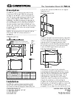
Step 1 –
Remove any knockouts from
the back box needed for cable egress.
Fasten the conduit connector to the
back box through the now open
knockout (Figure 1).
Step 2 – Remove the ceiling tile and cut an 11" x 9" opening. Be
sure to center the opening along the centerlines of the tile. (Figure
2).
Page 2
Step 3 – Place the tile back in the ceiling with the
back box and tile bridge over top. Attach the
hanger wires to the four tabs located on the
corners of the back box and then to a permanent
structure within the ceiling. Slide the cables
through the conduit connector and snap the
Firestop Grommet over the cables (Figure 3).
Make sure there is enough slack in the cabling to
attach to the access point.
NOTE:
A surface mount box (or biscuit jack) and
equipment cord can be conveniently mounted
inside the Model 1044. (Non-plenum rated cables
can be used inside a plenum rated enclosure).
Use an adhesive backed surface mount box.
Consider bend radius of horizontal cable and
equipment cord when attaching the surface mount
box.
Step 4 – To attach the access point to the trim, first remove
the two hex nuts that hold the aluminum mounting plate to
the painted trim piece. Next attach the Cisco AIR--
_BRACKET-2 to the mounting plate using the four (4)
screws provided. The Cisco mounting bracket should be
aligned so that the Ethernet jacks of the access point will
face toward the cut out area of Oberon mounting plate
(Figure 4).
Step 5 - After the Cisco mounting bracket has been installed
on the Oberon mounting plate, attach the Cisco 3800 to the
Cisco AIR-BRACKET-2. To finish the trim assembly, re-
attach the painted trim using the nuts removed in
Step 4
.
Page 3
Figure 1 -
Conduit Connector Installation.
Figure 2 -
Ceiling Tile Cutout.
Figure 4 -
AP and Trim Installation.
Figure 3
- Firestop Grommet Installation