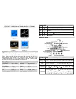
MODE
FAN
74
Off
Auto
F
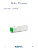
Model GC-TBZ48L
Battery Powered Z-Wave Plus
Thermostat
Installation & Operation Guide
PRINTER’S INSTRUCTIONS:
INSTR,INSTL,GC-Z-TBZ48L - P/N: 10006936 C- INK: BLACK - MATERIAL: 20 LB. MEAD BOND - SIZE: 8.500” X 5.500” - TOL. +/- 0.125”- SCALE: 1-1
FOLDING: ALBUM FOLD: BINDING: SADDLE STITCH
NOTE:
To take full advantage of this device's Z-Wave control capability you must purchase a compa ble
Z-Wave hub/controller. Remote control capability is provided via the hub/controller's remote control
app/so ware.
Summary of Contents for Gocontrol GC-TBZ48L
Page 31: ...Copyright 2017 Nortek Security Control LLC 29 ...
Page 32: ...10006936 C ...