GEM
-
TOUCH
Keypad Installation Instructions
1
push the wire back into the drilled wall center hole until the rear
case is flat against the wall surface. Insert screws through the
rear case mounting holes and secure.
If replacing an existing Gemini keypad:
Use the Wall Plate
Adapter instructions on page 2. Use the existing 4
-
wire or 14
-
pin harness.
If installing onto a double
-
gang box:
Insert mounting
screws through the two vertical elongated holes on the left side
of the case and into the box. If the box is visible when viewed
from the front, adjust the keypad vertically and tighten the
screws. Then, using hardware suitable for the mounting
surface, add one or two screws at the right side of the keypad
case directly into the wall.
Note:
Do not over tighten the mounting screws!
An uneven
surface may cause the keypad case to distort.
Assemble the keypad by placing the top edge of the keypad
front case over the two hooks at the top of the rear case. Push
the bottom of the keypad until it snaps together.
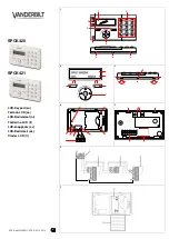
OPTION JUMPER
Cut wire loop
W1
to enable
S1
tamper switch.
DESCRIPTION
The GEMINI GEM
-
TOUCH keypad is compatible with the
NAPCO Gemini Series GEM
-
P816, GEM
-
P1632, GEM
-
P1664, GEM
-
P3200, GEM
-
X255 and GEM
-
P9600.
Note:
For
systems with multiple keypads, all keypads must be all
"classic" (GEM
-
RP prefix) or all "K Series" (GEM
-
K prefix).
Keypad types cannot be mixed.
SPECIFICATIONS
See product label.
Boot Current:
249mA peak
Nominal Operating Current:
148mA peak
Current During USB Update:
198mA peak
PGM:
Maximum 5mA, +12V nominal.
Environmental:
32°F to 122°F (0°C to 50°C)
INSTALLING THE KEYPAD
Requires power from the control panel bus (observe current
limitations) or an un
-
switched separate power supply (panel
ground must be common with power supply ground). Select a
location that allows the power wires to be hidden within the
mounting surface. Requires a battery backup power source to
avoid troubles if power is interrupted. Mount a keypad near
each exit/entry door (indoors locations only). In Residential
Fire Installations, Home Run all keypads.
Note:
The keypad
fire and panic buttons are not a substitute for a listed manual
initiating device (such as a pull box).
Do not power the keypad during the mounting process. De-
tach the rear case by pressing the two push
-
tabs at the bot-
tom, then unhook and detach.
For new installations:
Use the rear case as a template to
mark the mounting holes (always use a level to ensure hori-
zontal mounting). Mark the center hole for the power wire,
then use a 1/2" drill bit to drill the center hole. Snake the pow-
er wire inside the wall and out through the drilled center hole.
If mounting to hollow drywall or similar surface, we recommend
using wall anchors or similar hardware appropriate for the in-
stallation. Firmly connect the power wire connectors and then
GEM
-
TOUCH Keypad
Installation Instructions
© NAPCO 2021
WI2479CLF 12/21
333 Bayview Avenue, Amityville, New York 11701
For Sales and Repairs, (800) 645
-
9445
For Technical Service, (800) 645
-
9440 or visit us at
Tech.NapcoSecurity.com
(Note: Technical Service is for security professionals only)
Publicly traded on NASDAQ Symbol: NSSC
REMOTE BUS
All Zone End of Line
Resistors are 2.2K
Ω
BROWN
PGM
12V
(To control panel)
Tap/Hold-down
Tap/Hold-down
SYSTEM READY 1
09/14/28 8:15PM
(GEM
-
TOUCH Keypad)
WIRING FOR GEM
-
TOUCH
Disconnect power source before wiring to terminals
COLOR
FUNCTION
PANEL TERMINAL
RED
12V PWR
9
BLACK
PWR GND
10
GREEN
KEYPAD RX
11
YELLOW
KEYPAD TX
12
BROWN
PGM OUTPUT
Max 5mA, +12V Nominal
--
GRAY
ZONE COMMON
--
ORANGE
ZONE 1
--
BLUE
ZONE 2
--
GRAY
ZONE COMMON
--
VIOLET
ZONE 3
--
WHITE
ZONE 4
--
GRAY
ZONE COMMON
--
Important Note:
The GEM
-
TOUCH keypads cannot be used for control panel programming
.