


1
Air-conditioner Control System
Touch Controller TC-24A
Initial Setting Manual
For distribution to dealers and contractors only
This Initial Setting Manual contains information about the settings to be made at the time of installation. Please read the
instructions carefully and make the settings accordingly. Refer to the Installation Manual for how to install the TC-24A Touch
Controller, and refer to the air conditioning unit installation manuals for how to connect the controller cable to the air cond itioning
units, or how to install the air conditioning units. Please remember to give all manuals to the end users after installation is
complete.
1
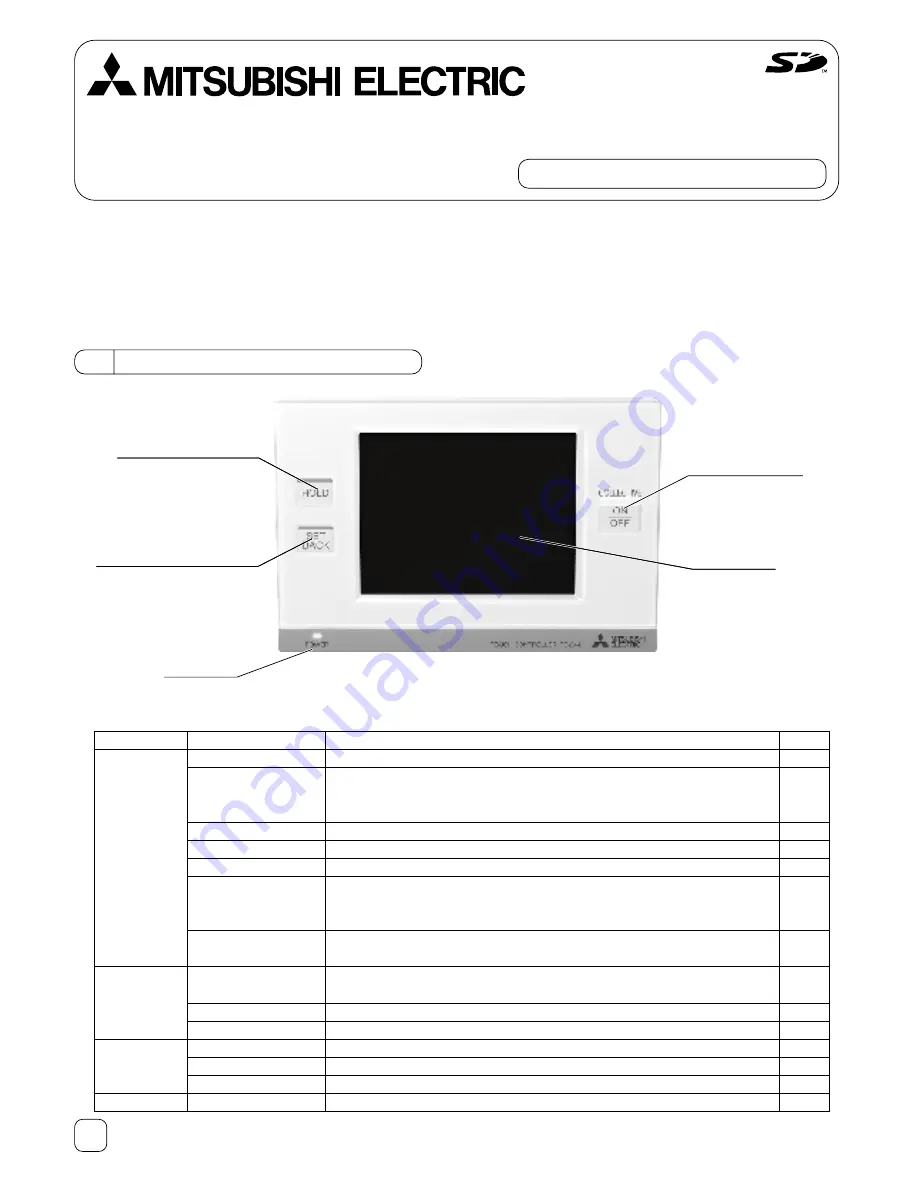
TC-24A Touch Controller
Function
Sets the M-NET address for the TC-24A.
Selects the type of controllers to prohibit access* from (remote controllers only
or both remote controllers and system controllers).
* Access to ON/OFF, Mode, Set Temp, and Filter Reset.
Selects the external input mode.
Displays or suppresses the Filter sign on the HOME screen.
Includes or excludes Dry mode as an option for the operation mode.
Selects the settable temperature range:
Standard: 67°F(19°C) to 83°F(28°C); Low: 46°F(8°C) to 87°F(30°C);
Manual: Settable to any arbitrary range between 46°F(8°C) and 87°F(30°C).
Sends or does not send the clock synchronization signal once a day to the
controllers and units.
Makes the group settings for the indoor units, LOSSNAY units, DIDO
controllers (PAC-YG66DCA), remote controllers, and sub-system controllers.
Enters the interlock settings between indoor and LOSSNAY units.
Deletes all group and interlock settings collectively.
Displays the information about the indoor units connected to each outdoor unit.
Stores the latest errors. (up to 50)
Updates software.
Runs a test on the connected air conditioning units.
Page
4
4
4
4
4
4
5
5
6
6
7
8
8
7
HOLD button with LED
SETBACK button with LED
Touch panel
Collective ON/OFF
button with LED
Power LED
Screen
Initial Settings
Basic System
Initial Settings
Groups
Maintenance
Test run
Setting
M-NET address
Remote controller
access
External input mode
Filter sign
Dry mode
Set temperature range
(Schedule)
Time notification
Groups
Interlocked operation
Batch deletion
System view
Malfunction log
Software update
Test run
List of functions available under the “Service menu”
2
2 TC-24A Screen Configurations
(1) Screen sequence and Service menu configuration
*1 A password is required to access the Service menu.
• The initial Service password is “9999.” Change the password as necessary to prevent unauthorized access.
• Make sure the password is available to the maintenance and other necessary personnel.
• The password can be set to an arbitrary number between four and eight digits.
• If you forget your password, log in with the master password.
Master password: 105638
• The same master password is used to log in to specific screens under the “Main Menu” and the “Service Menu.”
Touch [
].
Touch [
Touch [
].
Touch [
Touch [
].
Touch [
Touch [
].
Touch [
].
Touch [
].
Maintenance
Touch [
].
Touch [
].
Touch [
].
System view
Malfunction log
Software update
Test run
Groups
Interlocked LOSSNAY
Delete All
HOME screen
Service Menu screen
Touch [
].
Touch [
].
Initial settings/
Basic system
Initial settings/
Groups
Touch [
].
Main Menu screen
GRID (zoom-out) view
GRID (zoom-in) view
LIST view
GROUP view
Password Change screen
Icon
Button name
Main Menu
Service Menu
Password Change
Back
HOME
Cancel
Login
OK
Initial Settings/Basic system
Initial Settings/Groups
Maintenance
Test run
Groups
Interlocked LOSSNAY
Delete All
System view
Malfunction Log
Software Update
Login Page screen *1
Service Menu
*Touch [
] on each screen to return to a previous screen.
Touch [
].
Touch [
].
Touch [
].
Touch [
].
] or [
].
].
].
Touch [
].
3
3 Initial Settings
[Notes on using the TC-24A with the AG-150A controllers*]
In addition to making the group and interlock settings on the TC-24A, the same setting information must be entered on the AG-150A
controllers. Also, enter the M-NET address for the TC-24A in the System Controller field on the Group Setting screen. Register the
M-NET address of the AG-150A on the TC-24A's Group Setting screen.
When combining TC-24A with the AG-150A controllers, the Setback, Hold, and External Input Function settings should be made
only on the TC-24A. If using the Hold function on the TC-24A, schedule settings should not be made on the AG-150A controllers.
To prohibit the operation of local remote controllers, set the prohibition settings either from the TC-24A or AG-150A, but not both.
* AG-150A Controllers : AG-150A, GB-24A, GB-50A, G-50A
(1) Initial startup settings:
Before turning on the controller, first make sure that the controller, indoor units, and outdoor units have been installed
properly according to the instructions detailed in the respective manuals.
Turn on the controller and the units.
(a) The Language screen will appear
Ԙ
Select the display language.
ԙ
Touch the button to select the language of your choice.
Ԛ
Touch the OK button.
(b) The Date and Time screen will appear.
Ԙ
Set the current date on the Date tab, and set the current time on the Time tab,
using the ▼ and ▲ buttons to change the values.
ԙ
Click on the checkbox next to the date/time format of your choice.
Ԛ
Touch the Save button to save the settings.
(c) The Service Menu screen will appear.
Ԙ
Touch the Initial Settings/Basic System button to set the basic settings for the
controller. (Refer to section 3(2)-1 for details.)
ԙ
When the settings have been chosen, touch the Initial Settings/Groups button.
(d) The Initial Settings/Groups screen will appear.
Ԙ
Touch the Groups button to make the group settings. (Refer to 3(2)-2 for
details.)
ԙ
Touch the Interlocked LOSSNAY button to make the interlocked operation
settings. (Refer to 3(2)-3 for details.)
The initial startup settings are now complete.
Ԛ
Touch HOME button [ ] at the top right corner of the screen.
ԛ
Touch the OK button on the popup screen to start the initialization process.
(e) The message (shown left) will appear on the screen, displaying the
initialization progress. When initialization is complete, the screen will
automatically return to the HOME screen.
(Initialization will take up to five minutes.)
* To change settings later, perform a test run, or verify the maintenance
information
Ԙ
Touch MAIN MENU button [ ] on the HOME screen.
ԙ
Touch SERVICE MENU button [ ] on the Main Menu screen.
Ԛ
Enter the password to log on to the Service Menu screen.
(Refer to Chapters 3, 4, and 5.)
4
External Input Mode
1) Press the External Input setting button (labeled
Ԙ
in the figure) to select
between “Not used”,“Emergency Stop (Level signal),” “ON/OFF (Level
signal),” and “ON/OFF/Prohibit/Permit (Pulse signal).”
* Refer to the Installation Manual for detailed information on how to connect
the TC-24A to external devices.
Set Temperature Range (Schedule)
Set the temperature range that is available from the Set Schedule screen.
1) Touch the Set Temperature Range button (labeled
Ԙ
in the figure) to switch
between Standard, Low, and Manual.
The temperature set range for each option is shown below:
Standard : 67ºF(19ºC) to 83ºF(28ºC)
Low
: 46ºF(8ºC) to 87ºF(30ºC)
Manual : Can be set to any arbitrary range between 46ºF(8ºC) and
87ºF(30ºC)
2) When “Manual” is selected, set the lower and upper temperature limits
using the up and down arrows (labeled
ԙ
in the figure).
(2) Other Initial Settings
(2)-1. Basic controller setting
Touch Initial Settings/Basic System button [ ] on the Service menu screen to
access the Initial Settings/Basic System screen.
Touch Page turn button [ ][ ] to turn the pages, and follow the directions
below to make the settings for each group.
M-NET Address
1) Touch the M-NET Address button (labeled
Ԙ
in the figure), and set the
TC-24A Controller address on the screen that pops up.
● The address can be set to 000 or to a value between 201 and 250 (the
factory setting is 201).
Remote Controller Access
1) Touch the Remote Controller Access setting button (labeled
ԙ
in the figure)
to switch between “SC/RC” and “RC only.”
● Select “SC/RC” to prohibit access* from both the system controllers and
remote controllers, and select “RC only” to prohibit access from only the remote controllers.
* Access to ON/OFF, Mode, Set Temp, and Filter Reset.
Filter Sign Display
1) Press the Filter Sign Display button (labeled
Ԙ
in the figure) to switch
between ON and OFF.
● Setting this item to OFF will remove the Filter Sign from the HOME screen
display.
This item can be set to OFF if there is no need for the sign to appear on the
HOME screen; for example, in cases where filters are regularly changed
regardless of the filter sign status.
Dry Mode
1) Press the Dry Mode Setting button (labeled
ԙ
in the figure) to switch between
"Used" and “Not Used.”
● If this item is set to “Not Used,” the Dry mode will be unavailable for selection.
Ԙ
Ԙ
ԙ
Ԙ
ԙ
Ԙ
ԙ
Page turn button
Page No./No. of pages
Cannot set through TC-24A


