background image

 Micro one 230V 

 Micro one 24V 

Summary of Contents for Micro One 230

Page 1: ...Micro one 230V Micro one 24V ...

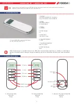
Page 2: ...A01 A02 A03 A00 ...

Page 3: ...A04c A04s A05 A06 A07 A08 A09 ...

Page 4: ...B01 B02 B03 B00 ...

Page 5: ...B04 B05 B06 B07c B07s B08 B09 ...

Page 6: ...D01 D02 D03 A B C D A B E ...

Page 7: ...after technical testing of the application Use only original accessories or accessories approved by Mingardi S r l to install the actuator IMPORTANT SAFETY REGULATIONS Warning Read this manual carefully Warning In order to ensure personal safety strictly comply with the regulations that are set out below USE AND MAINTENANCE When using the Micro One actuator follow these safety regulations Do not a...

Page 8: ...breakages of the window and injury to the operator A platform or scaffolding is provided if the actuators are to be installed at a height of more than 2 5 metres Operations to be carried out before installing the actuator Power up the actuator and have it perform one stroke to be sure that it was not damaged during transit Warning If safety components prevent the window from being fully opened or ...

Page 9: ...tom clamps code CD20302900 on the template for top hung windows code CD20302500 and lock them onto the template by screwing on the two screws code A020300400 1 M5x25 DIN 7984 without tightening them with force A04s Position this assembly while making sure that the spacers are all the way up against the frame and that they follow the profile for horizontal positioning make the centre line coincide ...

Page 10: ...tening screws supplied are only for aluminium frames Contact the Mingardi S r l technical service for wooden PVC or iron frames B04 B05 Use the two spyglasses pointed out in grey on the template for hopper frame windows for drilling on the wing which is necessary for fixing the hopper frame bracket code CD20303400 Use the same drill bit used for the previous drilling Remove the two spyglasses and ...

Page 11: ...se the two spyglasses on the template for hopper frame windows shown in grey for drilling on the wing which is necessary for fixing the hopper frame window bracket code CD20303400 Use the same drill bit used for the previous drilling Remove the two spyglasses pointed out in grey from the template for hopper frame windows using the initiation shown in darker grey as the breaking point B06 Loosen th...

Page 12: ...um height of 1 5 m If the actuator is expected to operate unattended automatic or remote operation it is advisable to install additional safety devices For connection to the electric system and signalling wires it is necessary that your carefully follow the instructions given on the side of the wiring diagrams contained in this manual Signalling with load is delivered in the following way 230V AC ...

Page 13: ...ly voltage shown on the rating plate Signalling contact with load Micro One 230VAC WIRES COLOURS COMPARATIVE TABLE COLOUR NUMBER SIGNAL BLUE 1 COMMON BLACK 2 CLOSES BROWN 3 OPENS WHITE 4 SIGNALLING RED 5 SIGNALLING C01 For single connection see figure C01 C02 For connection of more than one actuator see figure C02 C03 For connection of one or more actuators provided with signalling having fully cl...

Page 14: ...r supply voltage indicated in the rating plate data Signalling contact with load Micro One 24VDC WIRES COLOURS COMPARATIVE TABLE COLOUR NUMBER SIGNAL BLUE 1 POWER SUPPLY BLACK 2 SIGNALLING BROWN 3 POWER SUPPLY C04 For single connection see figure C04 C05 For connection of more than one actuator see figure C05 C06 For connection of one or more actuators provided with signalling having fully closed ...

Page 15: ...5 16 113 28 263 15 100 27 250 14 88 26 238 13 75 25 225 12 63 24 213 11 50 23 200 10 38 22 188 9 25 21 175 8 13 20 163 D02 Power up the actuator and make the entire chain go back in Power up the actuator and make the chain come out until the limit switch trips Check that the resulting stroke is the one you want the actuator stroke does not comprise the protrusion of the chain head If the stroke is...

Page 16: ...CE control unit 230V AC Batibus Actuator ratings plate 1M01 400 1 3 0 N 00 Maximum stroke Supply voltage No cable wires Type of fitting Colour Customised variations Family 3 Three wire cable 0 No fitting N Black 00 No variations ERRORS TO BE AVOIDED Class II insulation Actuator stroke thrust tensile force Working voltage frequency power absorbed for operation IP protection rating maximum continuou...

Page 17: ...itch Opening closing Hall effect diode Stroke 400mm Thrust force 200 N 200 N Tensile force 200 N 200 N Speed when empty 28mm s 32mm s Speed when loaded 26mm s 29mm s Continuous operation time 4 min 4 min Weight with without accessories 1 600 1 250 Kg 1 600 1 250 Kg Dimensions 358x60x44 IP protection rating 22 Product lifetime 10000 Variable stroke From 13 to 305mm with12 5mm pitches Operating temp...

Reviews: