


FORM: OM-890
Miller®
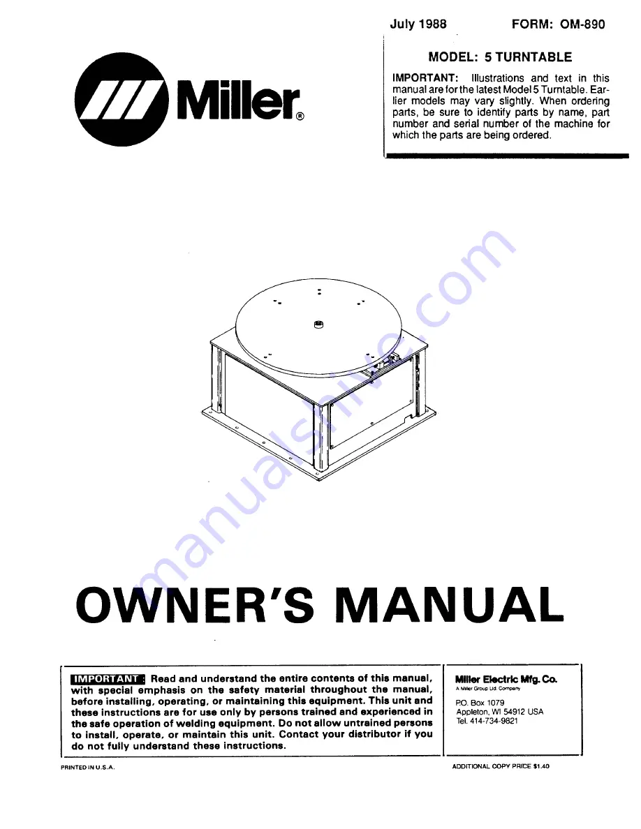
MODEL:
5 TURNTABLE
IMPORTANT:
Illustrations and text in this
manual are forthe latest Model 5 Turntable. Ear-
lier models may vary slightly. When ordering
parts, be sure to identify parts by name, part
number and serial number of the machine for
which the parts are being ordered.
OWNER’S MANUAL
IMPORTANT: Read and understand the entire contents of this manual,
with special emphasis on the safety material throughout the manual,
Mlflm Electric Mfg. Co.
AMd~, G,o,,~ Lid Co~’,p,nv
before installing, operating, or maintaining this equipment. This unit and
P0. Box 1079
these instructions are for use only by persons trained and experienced in
Appleton, WI 54912 USA
the safe operation of welding equipment. Do not allow untrained persons
Tel. 414-734-9821
to install, operate, or maintain this unit. Contact your distributor if you
do not fully understand these instructions.
July 1988
PRgNTED IN U.S.A.
ADDITIONAL COPY PRICE $1.40


