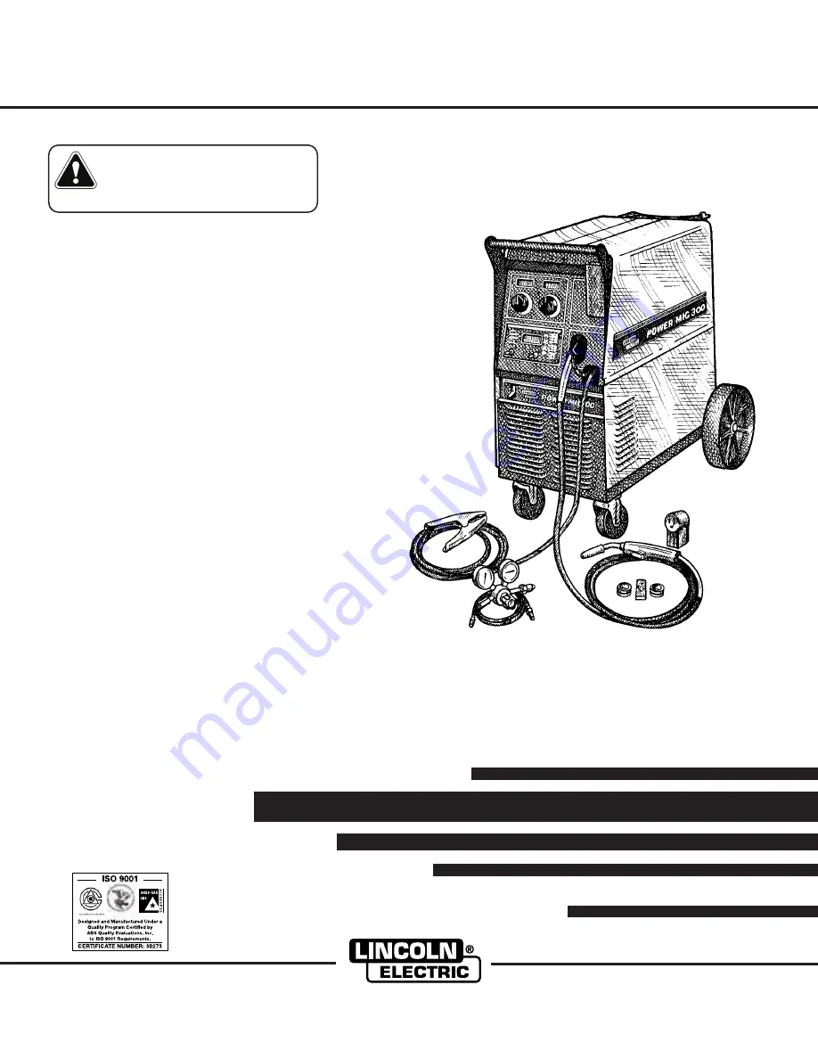
background image

POWER MIG

300

OPERATOR’S MANUAL

IM736-D

February, 2004

Safety Depends on You

Lincoln arc welding and cutting
equipment is designed and built
with safety in mind. However, your
overall safety can be increased by
proper installation ... and thought-
ful operation on your part.

DO

NOT INSTALL, OPERATE OR
REPAIR THIS EQUIPMENT
WITHOUT READING THIS
MANUAL AND THE SAFETY
PRECAUTIONS CONTAINED
THROUGHOUT.

And, most

importantly, think before you act
and be careful.

For use with machine Code Numbers: 10562, 10952, 10958, 11000, 11097, 11098

For use with machine

• Sales and Service through Subsidiaries and Distributors Worldwide •

Cleveland, Ohio 44117-1199  U.S.A.   TEL: 216.481.8100   FAX: 216.486.1751   WEB SITE: www.lincolnelectric.com

• World's Leader in Welding and Cutting Products •

Copyright © 2004 Lincoln Global Inc.

This manual covers equipment which is no 
longer in production by The Lincoln Electric Co.  
Specifications and availability of optional 
features may have changed.

Summary of Contents for POWER MIG 300

Page 1: ...ONTAINED THROUGHOUT And most importantly think before you act and be careful For use with machine Code Numbers 10562 10952 10958 11000 11097 11098 For use with machine Sales and Service through Subsidiaries and Distributors Worldwide Cleveland Ohio 44117 1199 U S A TEL 216 481 8100 FAX 216 486 1751 WEB SITE www lincolnelectric com World s Leader in Welding and Cutting Products Copyright 2004 Linco...

Page 2: ...R WEARERS SHOULD CONSULT WITH THEIR DOCTOR BEFORE OPERATING Read and understand the following safety highlights For additional safety information it is strongly recommended that you purchase a copy of Safety in Welding Cutting ANSI Standard Z49 1 from the American Welding Society P O Box 351040 Miami Florida 33135 or CSA Standard W117 2 1974 A Free copy of Arc Welding Safety booklet E205 is availa...

Page 3: ...ical earth ground 3 f Maintain the electrode holder work clamp welding cable and welding machine in good safe operating condition Replace damaged insulation 3 g Never dip the electrode in water for cooling 3 h Never simultaneously touch electrically hot parts of electrode holders connected to two welders because voltage between the two can be the total of the open circuit voltage of both welders 3...

Page 4: ...revent the welding sparks from starting a fire Remember that welding sparks and hot materials from welding can easily go through small cracks and openings to adjacent areas Avoid welding near hydraulic lines Have a fire extinguisher readily available 6 b Where compressed gases are to be used at the job site special precautions should be used to prevent hazardous situations Refer to Safety in Weldi...

Page 5: ...propriés et non inflammables 4 Des gouttes de laitier en fusion sont émises de l arc de soudage Se protéger avec des vêtements de protection libres de l huile tels que les gants en cuir chemise épaisse pan talons sans revers et chaussures montantes 5 Toujours porter des lunettes de sécurité dans la zone de soudage Utiliser des lunettes avec écrans lateraux dans les zones où l on pique le laitier 6...

Page 6: ...tion below for future reference This information can be found on your machine nameplate Product _________________________________________________________________________________ Model Number ___________________________________________________________________________ Code Number or Date Code_________________________________________________________________ Serial Number______________________________...

Page 7: ...tion C Drive Roll Kits C 1 Aluminum Feeding Kit C 1 Readi Reel Adapter C 1 Dual Cylinder Mounting Kit C 1 Alternative Magnum GMAW Gun and Cable Assemblies C 1 Magnum Gun Connection Kit C 1 Spool Gun PrinceTM XL C 1 Push Pull Feeding Connection Adapter Kit C 2 Making a Weld with the Prince XL or Cobra Gold Torch Installed C 2 _________________________________________________________________________...

Page 8: ...PUT OUTPUT RECOMMENDED INPUT WIRE AND FUSE SIZES SINGLE PHASE Height Width Depth Weight 31 79 in 18 88 in 38 78 in 255 Ibs 808 mm 480 mm 985 mm 116 kg PHYSICAL DIMENSIONS Wire Speed 50 700 IPM 1 27 17 8 m minute WIRE SPEED RANGE Standard Voltage Frequency Input Current 230Amp Rated Output Input Current 300 Amp Rated Output 208 230 460 575 60 Hz 48 43 22 17 Amps 72 62 31 25 Amps Input Voltage Duty ...

Page 9: ...de and local code requirements This welder may be operated from a single phase line or from one phase of a two or three phase line 2 The POWER MIG 300 is supplied connected for 230 Volt Input If the welder is to be operated on another voltage it must be reconnected according to the instructions in Figure A 1 Read entire installation section before starting installation SAFETY PRECAUTIONS POWER MIG...

Page 10: ...cle or cable to the input power lines and the system ground per the U S National Electrical Code and any applica ble local codes See Technical Specifications at the beginning of this chapter for proper wire sizes For long runs over 100ft 30 48m larger copper wires should be used Fuse the two hot lines with super lag type fuses as shown in the following dia gram The center contact in the receptacle...

Page 11: ... of gun cable into the female casting through opening in front panel Make sure connector is fully inserted and tighten knurled screw 3 Connect the gun trigger connector from the gun and cable to the mating receptacle inside the com partment located above the gun connection made in step 2 above Make sure that the key ways are aligned insert and tighten retaining ring SHIELDING GAS For Gas Metal Arc...

Page 12: ...r is equipped with a plastic washer be sure it is seated for connection to the CO2 cylin der 5 Attach one end of the inlet gas hose to the outlet fitting of the flow regulator the other end to the POWER MIG 300 rear fitting and tighten the union nuts securely with a wrench 6 Before opening the cylinder valve turn the regula tor adjusting knob counterclockwise until the adjusting spring pressure is...

Page 13: ...ground Always wear dry insulating gloves FUMES AND GASES can be dangerous Keep your head out of fumes Use ventilation or exhaust to remove fumes from breathing zone WELDING SPARKS can cause fire or explosion Keep flammable material away Do not weld on closed contain ers ARC RAYS can burn eyes and skin Wear eye ear and body protec tion Observe all safety information throughout this manual DEFINITIO...

Page 14: ...ergically change many variables so that as the WFS is changed the arc length and arc appearance will remain the same The synergic modes are usable with both push and push pull torches as described later in this Manual When using a spool gun however although the synergic pulsed modes are still accessible they must be used in a non synergic manner as described in the Accessory Section The digital mi...

Page 15: ... value depending on the status of the machine Located below the display is the text Volts and Trim An LED light is illuminated to the left of one of these in order to indicate the units of the value displayed in the meter CV Processes Prior to GMAW and FCAW operation the meter displays the desired preset Voltage value Prior to synergic GMAW P and GMAW PP oper ation the meter displays the desired p...

Page 16: ...ns that the machine is set for CC GTAW TIG welding Toggle the SELECT switch to activate the weld parame ters for the selected weld mode Set each parameter using the SET switch to adjust the parameter displayed on the display meter NOTE If the LED next to the weld parameter is flashing the WFS AMP and or the Volt Trim values can also be adjusted for that parameter using the control knobs below each...

Page 17: ...ents Run In The Run In function offers the ability to set a wire feed speed from trigger until an arc is established that is inde pendent of the Welding or Start wire feed speed Setting a Run In WFS lower than the welding WFS avoids stubbing problems when starting the arc Run In is selected by toggling the SELECT switch until the LED next to RUN IN is lit A Run In WFS may be adjusted using the SET...

Page 18: ...n dioxide are usu ally employed The added energy is associated in this sce nario with increasing the inductance negative numeric val ues By adding to the energy level the weld bead appear ance improves spatter levels decrease and wetting action at the toes of a fillet weld increases The arc is softer with the higher inductance setting and the arc lends itself to faster travel speed In GMAW P the p...

Page 19: ...rs the ability to set an endpoint for WFS and Voltage that will be reached over a specified time period At the end of the weld when the trigger is released the crater timer will begin and the WFS and Volts settings will ramp down from the Weld Mode WFS and Voltage settings to the Crater WFS and Voltage set tings over the time selected This creates a ramp down of the WFS and Volts during the Crater...

Page 20: ...comes off the reel in a direction so as to de reel from the top of the coil CAUTION PROCEDURE FOR CHANGING DRIVE AND IDLE ROLL SETS 1 Turn off the power source 2 Release the pressure on the idle roll by swinging the adjustable pressure arm down toward the back of the machine Lift the cast idle roll assembly and allow it to sit in an upright position 3 Remove the outside wire guide retaining plate ...

Page 21: ...um idle roll pressure varies with type of wire wire diameter surface conditions lubri cation and hardness As a general rule hard wires may require greater pressure and soft or aluminum wire may require less pressure than the factory set ting The optimum idle roll setting can be determined as follows 1 Press end of gun against a solid object that is elec trically isolated from the welder output and...

Page 22: ...ET OF WELD MATERIAL Pulsed MIG is an advanced form of welding that takes the best of all the other forms of transfer while minimiz ing or eliminating their disadvantages Unlike short cir cuit pulsed MIG does not create spatter or run the risk of cold lapping The welding positions in pulsed MIG are not limited as they are with globular or spray and its wire use is definitely more efficient Unlike t...

Page 23: ...the Arc Control increases the droplet trans fer and weld deposition rate Since Arc Control varies weld droplet transfer rate the Arc Control can be used to vary the ripple spacing in the weld bead BENEFITS OF PULSE ON PULSE FROM LINCOLN ELECTRIC Excellent appearance of the weld bead Improved cleaning action Reduced porosity Table B 3 shows WFS and Trim settings for common aluminum types and wire s...

Page 24: ...hen adjust the Volts Trim knob as follows For steel listen for the traditional frying egg sound of a good short arc MIG procedure to know you have the process set correctly For aluminum simply adjust the Volts Trim knob until the desired arc length is obtained Note the Volts Trim display is simply a relative number and DOES NOT correspond to voltage Some procedure recommendations appear in Table B...

Page 25: ...TM XL When the POWER MIG Gun Selector Switch is in the Standard Spool Gun position the POWER MIG pro vides gun trigger switch transfer between the Magnum gun or the spool gun for the same polarity welding with different wire and gas processes Closing either gun trigger will cause the electrode of both guns to be electrically HOT Be sure unused gun is positioned so electrode or tip will not contact...

Page 26: ...lue at the POWER MIG 300 to a value lower than the actual WFS Remember The dialed in SPD value at the POWER MIG 300 does not control the WFS at the spool gun Rather it is adjusting the POWER MIG 300 synergic work point Therefore adjusting the SPD value will not change your actual WFS at the spool gun WFS can only be changed at the spool gun PUSH PULL FEEDING CONNECTION ADAPTER KIT K2154 1 The push...

Page 27: ...10 minutes of arc time or as required GUN CABLE CLEANING To help prevent feeding problems clean cable liner after using approximately 300 pounds 136 kg of electrode Remove the cable from the wire feeder and lay it out straight on the floor Remove the contact tip from the gun Using an air hose and only partial pres sure gently blow out the cable liner from the gas dif fuser end SAFETY PRECAUTIONS E...

Page 28: ... INSTALLATION AND TRIMMING INSTRUCTIONS FOR MAGNUM 300 NOTE The variation in cable lengths prevents the interchangeability of liners between guns Once a liner has been cut for a particular gun it should not be installed in another gun unless it can meet the liner cutoff length requirement Liners are shipped with the jacket of the liner extended the proper amount 1 Remove the gas nozzle 2 Remove th...

Page 29: ...SIBLE CAUSE lists the obvious external possibilities that may contribute to the machine symptom Step 3 RECOMMENDED COURSE OF ACTION This column provides a course of action for the Possible Cause generally it states to contact your local Lincoln Authorized Field Service Facility If you do not understand or are unable to perform the Recommended Course of Action safely contact your local Lincoln Auth...

Page 30: ...reakers are properly sized See installation section of the manual for recommended fuse and breaker sizes 2 Welding procedure is drawing too much output current or duty cycle is too high Reduce output current duty cycle or both 3 There is internal damage to the power source Contact an autho rized Lincoln Electric Service facility 1 Make certain that the power switch is in the ON position 2 Input vo...

Page 31: ...ame plate rating and reconnect panel configuration 2 Make sure settings for wire feed speed and voltage are correct for process being used 3 Make sure output polarity is cor rect for process being used 4 Check welding cables and gun assembly for loose or faulty con nections 1 Make sure settings for wire feed speed and voltage are correct for process being used 2 The Run In Fast or Slow speed may b...

Page 32: ...cable or gun cable may be dirty 3 Check drive roll tension and position of grooves 4 Check for worn or loose drive rolls 5 The electrode may be rusty or dirty 6 Check for damaged or incorrect contact tip 7 Check wire spindle for ease of rotation and adjust break ten sion knob if necessary 1 Check the wire feed drive rolls and motor for smooth operation 2 Check for restrictions in the wire feed pat...

Page 33: ...er is pulled the problem is within the POWER MIG 300 5 Make sure the gun is pushed all the way into gun mount and is properly seated RECOMMENDED COURSE OF ACTION If all recommended possible areas of misadjustment have been checked and the problem persists Contact your local Lincoln Authorized Field Service Facility GAS FLOW PROBLEMS If for any reason you do not understand the test procedures or ar...

Page 34: ...rdware fault 2 81 Motor overload average motor Verify motor armature is not current exceeded 8 00 amps for binding Verify Wire Spool more than 0 50 seconds is not binding 82 Motor overcurrent average motor Verify wire can move freely in current exceeded 3 50 amps for cable Verify Spool Brake is not more than 10 0 seconds set to tight Displays Description Scrolling dash Appears at power up while th...

Page 35: ...spindle brake Refer to the push pull connection kit for this spacer 3 Check the wire at the spool Make sure wire is not crossed and is de reeling properly 4 Increase wire feed speed to 350 400 ipm 5 If problem continues after a thru d are checked then the Stall Factor Number needs to be increased See Stall Factor Number Adjustment 1 Check torch cable for kinks Torch cable should be laid out relati...

Page 36: ...lightly to help the wire jump the gap 3 Slow down wire feed speed while pushing wire through torch liner Recommend setting 350 ipm 4 If problem continues after a thru c are checked then the Stall Factor Number needs to be decreased See Stall Factor Number Adjustment 1 PM 300 drive rolls set too tight The tension arm should be set at 1 to 1 1 2 2 Check to see that the spindle brake is not set too t...

Page 37: ...d be set at 1 to 1 1 2 3 Push Pull torch drive rolls set too tight Refer to owners manual for proper setting 4 If pulse welding the trim value may be set too high 5 Clean or replace contact tip 6 If problem continues after a thru e are checked then the Stall Factor Number needs to be increased See Stall Factor Number Adjustment 1 Torch liner conduit not inserted all the way so that it is touching ...

Page 38: ...he rear drive motor to pull the wire off the spool and get the wire up the torch liner STALL FACTOR NUMBER ADJUSTMENT 1 Turn the POWER MIG 300 off 2 Hold the Push Pull Torch trigger in and turn the power back on Continue to hold the trigger in while machine powers up 3 Once the machine displays SF in the left display and a number 5 to 35 in the right display the trigger can be released 4 Use the v...

Page 39: ...B 834 833 836 835 GAS SOLENOID 833 834 806 804 802 801 716 715 615 604 607 604 412 411 410 408 407 406 405 403 402 401 WIRE DRIVE MOTOR GEARBOX TO STUD 901 903 502 BRIDGE DIODE FAN MOTOR ENCODER P C BOARD DISPLAY P C BOARD FLEX 50 watts 500 ohms 2520 2530 471 472 412 411 408 407 403 406 402 405 410 401 901 903 715 716 LEM 1 2 3 4 802 804 801 806 STUD STUD 502 503A FAN RELAY FAN L1 CHOKE RECONNECT ...

Page 40: ...408 407 406 405 403 402 401 WIRE DRIVE MOTOR GEARBOX TO STUD 901 903 502 BRIDGE DIODE FAN MOTOR DISPLAY P C BOARD 50 watts 500 ohms 2520 2530 471 472 412 411 408 407 403 406 402 405 410 401 901 903 715 716 LEM 1 2 3 4 802 804 801 806 STUD STUD 502 503A FAN RELAY FAN L1 CHOKE RECONNECT PANEL LINE SWITCH H1 H2 H5 H3 H4 115V X3 X4 X1 X2 H1 H4 L2 L1 H1 W B G L1 L2 H5 H2 H3 H4 1 2 3 4 5 6 J88 MSP III B...

Page 41: ... covered by this manual The specific diagram for a particular code is pasted inside the machine on one of the enclosure panels If the diagram is illegible write to the Service Department for a replacement Give the equipment code number WIRING DIAGRAM POWER MIG 300 FOR CODES 10958 AND 11000 POWER MIG 300 ...

Page 42: ... 3234 472 471 3233 471B 472B L3 B W L2 L7 L6 1104 1103 503 503A B6 B2 B5 B1 B5 1 2 3 4 5 6 7 20 253 254 251 254 253 251 SHIELDED CABLE S3 RS232 CONNECTOR SHIELDED CABLE P C BOARD CONNECTION DETAIL J37 FLEX CONTROL BOARD FLEX CIRCUIT SHIELDED CABLE H1 H4 H1 L9 PANEL ENCODERS VOLTS TRIM WFS AMPS 858 857 859 8510 1 2 3 1 2 3 16 15 14 13 12 11 10 9 8 7 6 5 4 3 2 1 J85 8512 852 851 8511 855A G4511 1 2 ...

Page 43: ...DIMENSION PRINT F 5 POWER MIG 300 F 5 3 00F M19231 ...

Page 44: ...NOTES POWER MIG 300 ...

Page 45: ...NOTES POWER MIG 300 ...

Page 46: ...electrically live parts or electrode with skin or wet clothing Insulate yourself from work and ground No toque las partes o los electrodos bajo carga con la piel o ropa moja da Aislese del trabajo y de la tierra Ne laissez ni la peau ni des vête ments mouillés entrer en contact avec des pièces sous tension Isolez vous du travail et de la terre Berühren Sie keine stromführenden Teile oder Elektrode...

Page 47: ...gute Be und Entlüftung des Arbeitsplatzes Mantenha seu rosto da fumaça Use ventilação e exhaustão para remover fumo da zona respiratória Turn power off before servicing Desconectar el cable de ali mentación de poder de la máquina antes de iniciar cualquier servicio Débranchez le courant avant l entre tien Strom vor Wartungsarbeiten abschalten Netzstrom völlig öff nen Maschine anhalten Não opere co...

Page 48: ...s and Service through Subsidiaries and Distributors Worldwide Cleveland Ohio 44117 1199 U S A TEL 216 481 8100 FAX 216 486 1751 WEB SITE www lincolnelectric com World s Leader in Welding and Cutting Products ...

Reviews: