


LevNet RF Receptacle (Tamper-Resistant)
Cat. Nos. WSG15-0DZ (Top Controlled), WSG15-TDZ (Dual Controlled, Title 24)
Ratings: 125VAC, 60Hz, 15A
Switched: 15A General Use/Resistive, 1800W Incandescent, 1800VA Inductive, 1/2HP, 120VAC
INSTALLATION AND QUICK START GUIDE
WARNINGS AND CAUTIONS:
•
TO AVOID FIRE SHOCK OR DEATH; TURN OFF POWER at circuit
breaker or fuse and test that power is off before wiring, servicing,
installing or removing device.
• To be installed and/or used in accordance with electrical codes and
regulations.
• If you are unsure about any part of these instructions, consult an
electrician.
• To ensure that there is adequate room for wires, Leviton recommends
using 3-1/2 inch deep wall boxes, at a minimum. For single-gang
applications, this would be an 18-cubic inch wall box, at a minimum.
• Use this device with
copper or copper clad wire only.
DESCRIPTION
The LevNet RF Receptacle (WSG15) is designed to use wireless
communication and provide remote control of your lighting. The device
will control lighting or equipment attached to the receptacle by receiving
a wireless signal (315MHz) from other EnOcean enabled wireless
devices.
Devices can be learned directly into the unit via the Programming
Mode Selection Menu or wireless via the Leviton ComWi software and
WSCOM-03W.
The WSG15 receptacle has a 50-100 ft. reception range depending
upon the environment and transmission device. Range will be reduced
by signals having to transmit through walls.
NOTE: Some motorized
devices, such as a power drill, can significantly reduce the effective
range of the WSG15.
Transmit range for WSG15, when utilized as a repeater or for initial
setup/commissioning is between 20-50 ft.
FEATURES
• Able to switch single (WSG15-0DZ) or dual (WSG15-TDZ) outlets
ON/OFF remotely
• Scene Capable
• ON/OFF LED
• Can be remotely configured and commissioned using the LevNetRF
ComWi software and EnOcean WSCOM hardware
• Includes repeater function (Level 1 or 2) to increase wireless
reception to other devices
• Ease of installation – No new wiring
• Built-In tamper resistant barrier designed to limit improper insertion of
small objects into receptacle contact slots
COMPATIBLE DEVICES
Most EnOcean Alliance enabled devices which conform to the EnOcean
Equipment Profile (EEP) are compatible with the WSG15 receptacle.
This includes but is not limited to room controllers, occupancy sensors,
key cards, unpowered switches, door and window sensors made by
Leviton as well as other EnOcean Alliance companies which support
EEP 2.1 and above.
EQUIPMENT NEEDED FOR INSTALLATION
• Slotted/Phillips Screwdriver
• Pencil
• Electrical Tape
• Cutters
• Pliers
• Ruler
INSTALLATION
Changing the color of your receptacle:
Your receptacle includes five color options. The receptacle ships with the
white frame attached. To change color of the frame, proceed as follows:
WARNING: TO AVOID FIRE SHOCK OR DEATH; TURN OFF
POWER at circuit breaker or fuse and test that power is off
before wiring!
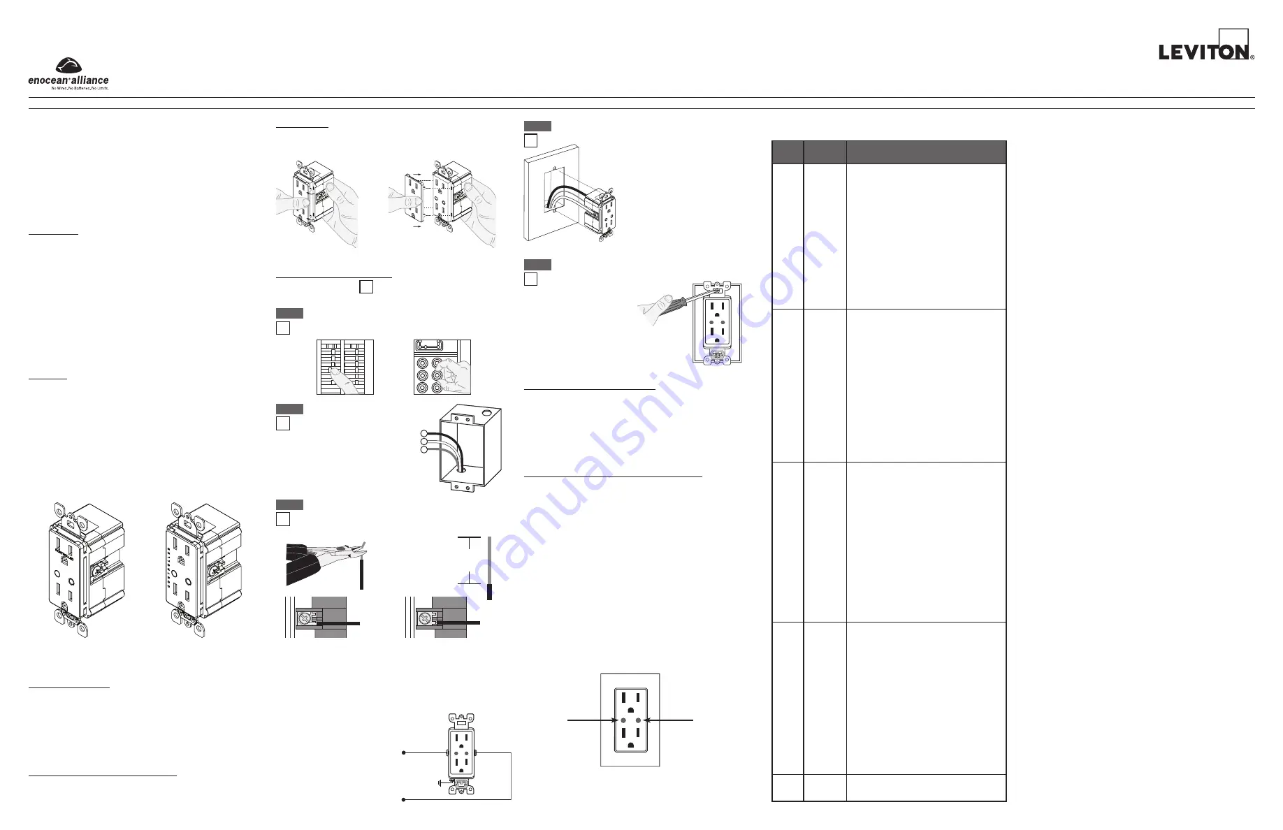
Step 1
INSTALLING YOUR RECEPTACLE
NOTE: Use check boxes when Steps are completed.
Connect wires per WIRING
DIAGRAM as follows:
• Green or bare copper wire in wall
box to Green terminal screw.
• Line Hot wall box wire to terminal
screw (Black) marked "LINE".
• Line Neutral wall box wire to
terminal screw (Silver) marked
"NEUTRAL".
• Proceed to Step 4.
INSTALLING SOFTWARE (OPTIONAL)
For additional details refer to the ComWi Installation & Operation
instructions. Consult the factory for details.
DI-000-WSG15-02A-X5
Single Controlled Top Outlet
Dual Controlled Outlets
Push in side at tab to
release
Line up tabs and press in sides
one at a time to attach
ON
OFF
ON
OFF
ON
OFF
ON
OFF
ON
OFF
ON
OFF
ON
OFF
ON
OFF
ON
OFF
ON
OFF
ON
OFF
ON
OFF
Wiring the receptacle:
This receptacle can be wired using side wire terminal screws
or through backwire openings. Choose appropriate wire
stripping specifications accordingly.
Step 3
Side Wire Connection
Side wire terminals accept
#14-12 AWG solid copper
wire only.
Back Wire Connection
(either hole may be used)
Back wire openings accept #14-12
AWG solid copper wire only.
• Make sure that the ends of the wires from the wall box are straight
(cut if necessary).
• Remove insulation from each wire in the wall box as shown.
5/8"
(1.6 cm)
Strip Gage
(measure bare
wire here)
Cut
(if necessary)
Identifying your wiring
application (most common):
NOTE: If the wiring in your
wall box does not resemble
this configuration, consult an
electrician.
Step 2
1
2
3
Single Pole
1. Line (Hot)
2. Neutral
3. Ground
Step 4
Testing your Receptacle prior to mounting in wall box:
• Position all wires to provide room in
outlet wall box for device.
• Partially screw in mounting screws in
wall box mounting holes.
NOTE: Dress wires with a bend as
shown in diagram in order to relieve
stress when mounting device.
• Restore power at circuit breaker or fuse.
• The green Locator light should turn ON.
If locator light does not turn ON,
refer to the TROUBLESHOOTING
section.
Neutral (Silver)
Line (Black)
Green
Ground
CONTROLLED
Step 5
Receptacle Mounting:
TURN OFF POWER AT CIRCUIT BREAKER OR FUSE.
• Installation may now be
completed by tightening
mounting screws
into wall box. Attach
wallplate.
• Restore power at
circuit breaker or
fuse.
Installation is
complete.
CONTROLLED
Programming Instructions:
All devices are learned in a "reduced sensitivity" mode to avoid
interference from other devices which may be active in areas close by.
This reduction of sensitivity reduces the range so devices learned to the
WSG15 receptacle should be within 10 ft when learning.
Factory Defaults (only accessible via ComWi software):
• Occupancy Sensor Timeout: 20 minutes
• Momentary Egress Delay: 0 seconds
• Repeater Mode: ON, Level 1
Time-Outs:
When used with an occupancy sensor the WSG15 has six time-out
settings: 2, 5, 10, 15, 20, or 30 min. (a longer timeout is recommended
when using self powered devices in dark spaces). The values of time-
out defaults to 20 minutes and can only be changed using the ComWi
software with WSCOM tool.
Walk-Through Time Delay:
The walk-through feature is only active in the Auto-On/Auto-Off mode
with time delay > 2 minutes. This feature is useful when a room is
momentarily occupied. When enabled, the Sensor will turn the lights
OFF shortly after the person leaves the room. The walk-through feature
works in the following manner: When a person enters the room, the
lights will turn ON. If the person leaves the room before the walk-through
time-out of 2.5 minutes, the Sensor will turn the lights OFF within 2.5
minutes of no occupancy detected. If the room is occupied for longer
than 2.5 minutes, the Sensor will enter the Occupied Mode with the
time-out duration specified by Factory Default settings or configuration
set by the ComWi software.
Locator Light
Programming Button
CONTROLLED
There are five distinct programming modes, each represented by a
different Amber Blink:
1
Rocker
• Door and Window Sensors – "Normal"
mode. OPEN = OFF (magnet is not near
sensor), CLOSED = ON (magnet near
sensor).
• Switches – Sets the device to use the "I"
side to turn the light ON and the "O" side to
turn the light OFF. Acts light normal rocker
light switch.
• Occupancy sensor – Manual-ON/Auto-
OFF mode which turns the light OFF when
unoccupied. Has a 30 second Vacancy
period before lights can only be turned ON
via switch. Default delay time is 20 minutes.
• SLT Device – "Normal" mode. Similar to
a switch which turns lights ON and keeps
lights ON when active.
Amber
Blinks
Details
Mode
2
Momentary • Door and Window Sensors – "Inverted"
mode. OPEN = ON (magnet is not near
sensor), CLOSED = OFF (magnet near
sensor).
• Switches and Key Cards – Press turns
the lights ON and release turns them OFF.
Intended for key card devices to turn lights
ON when card is inserted and OFF when
removed. Only applies to the actual button
pressed on the device (ignores the other
side of a Decora
®
rocker switch).
• Occupancy sensor – Auto-ON/Auto-OFF
mode. Turns lights ON with detection
of occupancy and lights OFF when
unoccupied (after time delay). Default delay
time is 20 minutes.
3
Toggle
• Door and Window Sensors – "Inverted"
mode. OPEN = ON (magnet is not near
sensor), CLOSED = OFF (magnet near
sensor).
• Switches/Key Cards – The state of the lights
will toggle with the press of the switch or
insertion of a Key Card. Only applies to
the actual button pressed on the device
(ignores the other side of a Decora
®
rocker
switch). Removing the Key Card will be
ignored.
• Occupancy sensor – Auto-ON/Auto-OFF
mode with 2.5 minute Walk-Thru Enabled.
Turns lights ON with detection of occupancy
and lights OFF when unoccupied. Default
delay time is 20 minutes.
4
Scene
• Door and Window Sensors – "Inverted"
mode. OPEN = ON (magnet is not near
sensor), CLOSED = OFF (magnet near
sensor).
• Switch and Key card devices – Restores
the state of the lights to what they were
when the device was learned. Only applies
to the actual button pressed on the device
(ignores the other side of a Decora
®
rocker
switch).
5
Clear All
• Clears all devices from memory and returns
device to factory default configuration.
NOTE: If a NEW occupancy sensor is learned, then all learned
occupancy sensors for that unit will default to this current state learned.
For example, if the first occupancy sensor is learned as Manual-ON/
Auto-OFF and the second occupancy sensor is learned to Auto-ON/
Auto-OFF, then all occupancy sensors will default to the last learned
occupancy state, which is Auto-ON/Auto-OFF in this case.
Follow these directions for the standard way to program and configure
the WSC15 Receptacle.
1. Enter Programming Mode by pressing and holding the Programming
Button for 15 Seconds until the LED on the receptacle begins flashing
Amber slowly 1x per second. This is the Mode Selection Menu of
programming.
2. Press the Programming Button to advance between the five
programming modes. The Amber LED will blink to represent the
Programming Mode.
3. Press and hold the Programming Button 3-5 seconds to enter the
desired Programming Learn Mode. The LED will blink Red (empty)
or Green (memory) upon entering the Programming Learn Mode.
4. Press the Programming Button for 1-2 seconds to leave the
programming mode and go back to the Mode Selection Menu
(Amber blink).
5. Device will exit Programming Mode after 20 seconds of inactivity.
NOTE: Amber flashing LED represents the Mode Selection Menu
of programming. No buttons can be learned into a receiver with
Amber flashing lights. A Red or Green flashing LED represents the
Programming Learn Mode.
Rocker Mode Programming Instructions
(LED flashing Amber 1x per second)
1. Upon entering Programming Mode, the device will automatically
begin in Rocker Mode (Amber LED flashing 1x per sec).
2. To Learn a device in Rocker Mode press and hold the Programming
Button for 3-5 seconds until the LED changes from Amber to Red or
Green to signify you are now in the Programming Learn Mode.
3. When learning a wireless switch to the LevNet RF Receptacle,
press one end of a switch rocker. When learning a transmitter other
than a wireless switch or keycard, press the LEARN button on the
transmitter
(see appropriate transmitter instruction sheet).
The LED on the receptacle will turn Amber and the load will toggle
states for 2 seconds indicating that the receptacle has stored the
transmitter’s unique ID in its memory.
NOTE: The LED will change
from Flashing Red to Flashing Green on the first learned device
or increase the number of Green flashes to represent a device
was learned.
NOTE: Pressing the transmitter switch again will unlearn the unique
ID. The load will not toggle and the Green LED will light up for 2
seconds before going back to a Red or Green blink.
NOTE: If only one transmitter is desired then skip to Step 6.
4. To program additional transmitters to communicate with this
receptacle in Rocker Mode, wait until LED flashing resumes.
Repeat the instructions in Step 3 until the unique IDs of all desired
transmitters are stored in the Rocker Mode memory of the receiver
(up to 20). The Green tracking blinks for up to 20 devices learned,
however, the Programming Mode will exit after 20 seconds of
inactivity so it will not be possible to tell if 20 devices are learned.
5. To program additional transmitters to communicate with this receptacle
in another Mode, press the receiver switch/programming button and
return to the Mode Selection Menu (Amber LED flashing). The Amber
LED will be flashing 1x per second for Rocker Mode. Pressing the
receiver switch button will advance the Amber flashing to the next
Programming Mode, Momentary Mode (Amber flash 2x per second).
Follow Steps 3 and 4 to program transmitters to Momentary Mode.
6. To exit Learn Mode, just wait; the receiver automatically exits Learn
Mode after 20 seconds (indicated by the ceasing of the LED flashing).


