GreenMAX Relay System Cabinet
Cat. No. R08TC-100
For use with GreenMAX Relay Systems
WARNINGS AND CAUTIONS:
• To be installed and/or used in accordance with appropriate electrical codes and regulations.
• Installation and maintenance of this unit and the associated components requires an electrician.
• All relays must be installed on a Relay Insert Panel in a Leviton GreenMAX Relay Systems cabinet.
• The covers and lower ventilation plate must be in place when any circuit in the cabinet is energized.
INSTALLATION
English
DI-000-R08TC-00A-X2
To Install
MOUNT CABINET
1.
WARNING:
TO AVOID FIRE, SHOCK, OR DEATH;
TURN OFF POWER
AT CIRCUIT BREAKER OR FUSE AND
TEST THAT THE POWER IS OFF BEFORE WIRING!
2.
Securely mount enclosure to wall using fasteners appropriate for wall type.
NOTE:
Mounting holes are provided in the enclosure, the upper holes are keyhole slots to facilitate easy hanging.
Any field drilled mounting holes should be confined to the wire-way areas so that they do not obstruct the
installation of the Relay Insert Panels or the Command Module.
3.
Install all conduit runs and pull all lighting circuit and power wiring.
NOTE:
It is recommended that all wire be pulled prior to installing the Command Module and Relay Insert Panels.
This will prevent damage to the electrical components.
INSTALL COMMAND MODULE
1.
Install the Command Module by sliding the slots on the bottom of the Command Module over the mounting tabs
of the cabinet. Pass the Power Supply leads through the grommet to the power wiring area while installing. The
Command Module should be free to rotate forward and back without any obstruction. Fasten the Command
Module in place with the two screws provided
(see Detail on page 2)
.
2.
Connect the incoming Line, Neutral, and Ground wires of the designated power circuit, to the cabinet electronics.
NOTE:
This connection should be made in the power wiring area provided. If the source of power requires that
this area must be separated from other circuit conductors, install the metal partitions provided. The Neutral
connection must also include the Neutral wire from the uppermost Relay Insert Panel. A jumper is provided to
extend this conductor from the Relay distribution spine to the connection point.
3.
Connect the Equipment Grounding conductor to the grounding location provided adjacent to the system power
supply. Use the ground screw provided for this purpose.
4.
Using Cat 5 (or better) cables and RJ45 connectors, connect the Power Supply to both the MPU and the Low
Voltage input board using the designated ports.
NOTE:
If Low Voltage inputs are required, make these connections according to the diagrams provided for the
specific input type. To aid this process, remove the terminal blocks by pulling the green block straight out and
away from the module. Provide enough cable length to allow the unobstructed movement of the Command
Module.
INSTALL RELAY INSERT PANEL
1.
Position Relay Insert Panel on the locating tabs of the cabinet and fasten in place with the two mounting screws
provided at the top of the panel. Plug the ribbon cable into the Command Module. The Neutral jumper must be
extended to make a connection with the Power Supply neutral and the panel feed.
2.
Connect Line and Load to the relays according to the panel schedule provided in the document package.
NOTE:
Relay line and load terminals are suitable for wire sizes #6 to #14 AWG Copper solid or stranded.
Stranded wire should be tightly twisted before insertion into terminal.
WIRE LOW VOLTAGE INPUT CARD
1.
Wire Low Voltage wiring according to the device wiring diagrams.
NOTE:
Low Voltage wiring should be confined to the designated areas at the top of the enclosure. LumaCAN
wiring is interconnected with Cat5 (or better) cable and RJ45 connectors. All cables should be tested and verified
for proper operation before being connected to any components.
NOTE:
Areas at the top left and right corners of the enclosure can be used for either Low Voltage or High Voltage
wiring. Metal barriers are provided to segregate Lighting/ Power Wiring and Low Voltage wiring. These barriers
can be relocated as necessary.
NOTE:
Low voltage wire should be #14 - #24 AWG.
RATINGS:
• For relay ratings, see the Installation Sheet provided with either the Relay Insert Panels or the Individual relay.
•
The power requirement of the Command Module is: 100-277VAC 50/60Hz
• The load rating of the Power Supply of the Command Module is: 70W @ 24VDC +/-10%
• The cabinet is suitable for NEMA1 applications only (indoor use/not water or weather resistant).
3.
To test circuit, turn circuit breaker OFF, use the manual actuator handle to turn the relay to the Closed or ON
position and then turn circuit Breaker ON. This prevents damage to the relay if the circuit is shorted.
NOTE:
Individual relays can be relocated or added by aligning and inserting tabs on the base of the relay in the
slots provided in the back-plate. While inserted, slide the relay toward the center until completely engaged.
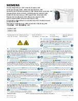
Relay Insert Panel
Cat Number: R0800-000
Relays
Cat Number:
RELAY-1CB
RELAY-1CS
RELAY-1TB
RELAY-1TS
RELAY-1DS
RELAY-2CB (SHOWN)
RELAY-2CS
RELAY-2TB
RELAY-2TS
Command Module
Cat Number:
RPM00-100
RPM08-108
RPM16-116
(SHOWN)
Enclosure
Cat Number:
R08TC-100
Multi-use Areas
Removable barriers
partition this area to
meet field requirements.
Mounting holes
Four (4) mounting holes
are provided in back of
cabinet. Upper holes are
slotted to ease installation.
Additonal holes may be
added in the wireway area
only. Avoid areas reserved
for the Relay Insert Panels
and the Command Module.
Conduit Entry
Conduits can enter
the cabinet on all four
(4) sides. Plan for Low
Voltage conductors at
the top of the enclosure.
Low Voltage Area
Lighting & Power Wireway
Relay Insert Panel Mounting Tab
Line Terminals
Phase 1
Phase 2
Load Terminals
Manual Actuator