First Edition, July 2015.
Copyright Lenovo 2015.
LIMITED AND RESTRICTED RIGHTS NOTICE:
If data or software is delivered pursuant a General Services Administration “GSA” contract, use, reproduction, or disclosure is subject to restrictions set forth in Contract No. GS-35F-05925.
Lenovo and the Lenovo logo are trademarks of Lenovo in the United States, other countries, or both.
Printed in USA
590-xxx-501A
Quick Installation Guide
Global Console Manager
GCM16 | GCM32
1
Before installing this product, read the
Safety Information and the Important
Notices and Warranty Information
document on the Documentation CD.
2
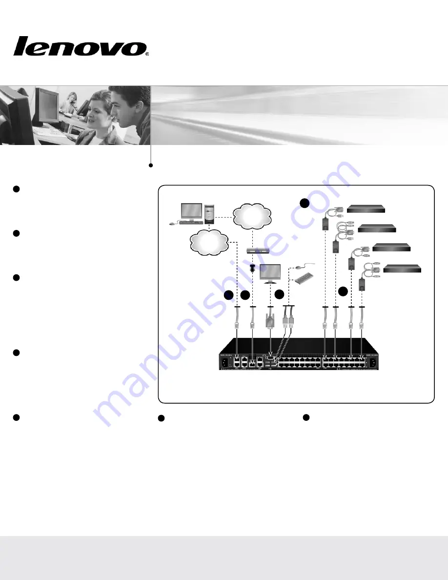
Connecting the local port
Connect your VGA monitor and USB keyboard
and mouse cables into the appropriately labeled
GCM16 or GCM32 switch ports.
3
Connecting a Conversion Option cable
to the GCM16 or GCM32 switch
Connect one end of a CAT 5 cable (4-pair, up
to 150 ft/45 m) into an available numbered
port on the rear of your GCM16 or GCM32
switch. Connect the other end into the RJ-45
connector of the Conversion Option cable.
4
Connecting a target device to a
Conversion Option cable
Connect a Conversion Option cable into the
appropriate port on the back of a target device.
Repeat steps 3 and 4 for all target devices you
want to connect.
5
Connecting network and remote users
Connect a customer supplied CAT 5 cable
from the Ethernet network into a LAN port on
the back of the GCM16 or GCM32 switch.
Network users will access the GCM16 or
GCM32 switch through this port.
6
Connecting to an external modem
(optional)
The GCM16 or GCM32 switch may also be
accessed using an ITU V.92, V.90 or V.24-
compatible modem. Connect one end of a CAT
5 cable into the MODEM port on the GCM16
or GCM32 switch. Connect the other end into
the CAT 5 to DB-9 (male) adapter, which then
connects into the appropriate port on the back
of the modem.
7
Connecting a supported PDU to the
GCM16 or GCM32 switch (optional)
Connect one end of the RJ-45 cable supplied
with the Power Distribution Unit (PDU) into the
PDU1 port on the GCM16 or GCM32 switch.
Using the supplied RJ-45 adapter, connect the
other end into the PDU. Connect the power
cords from the target devices into the PDU.
Connect the PDU into an appropriate AC wall
outlet. Repeat this procedure for the PDU2
port to connect a second PDU, if desired.
Connecting the GCM switch
GCM16 or GCM32 switch
(GCM32 shown)
Target devices
3
Ethernet
Telephone
network
Modem
Local USB
connection
IBM
Conversion
Option
2
4
5
6