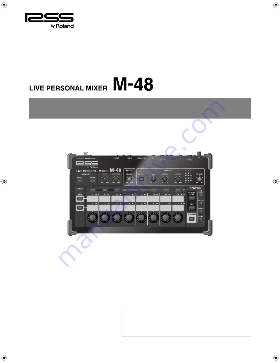
background image


Owner’s Manual


Copyright © 2009  ROLAND CORPORATION


All rights reserved. No part of this publication may be reproduced in any form without 

the written permission of ROLAND CORPORATION.

Before using this unit, carefully read the sections entitled: “USING THE UNIT SAFELY” 

and “IMPORTANT NOTES” (p. 5–6; p. 7). These sections provide important information 

concerning the proper operation of the unit. Additionally, in order to feel assured 

that you have gained a good grasp of every feature provided by your new unit, 

Owner’s Manual should be read in its entirety. The manual should be saved and kept 

on hand as a convenient reference.

M-48_e.book 1 ページ 2009年2月24日 火曜日 午前9時33分

Summary of Contents for M-48

Page 1: ...refully read the sections entitled USING THE UNIT SAFELY and IMPORTANT NOTES p 5 6 p 7 These sections provide important information concerning the proper operation of the unit Additionally in order to feel assured that you have gained a good grasp of every feature provided by your new unit Owner s Manual should be read in its entirety The manual should be saved and kept on hand as a convenient ref...

Page 2: ...48 main unit Mounting bracket bracket tray 1 Mounting bracket attachment kit Rubber washer 1 Wing nut for 3 8 inch screw 1 Washers for 3 8 inch screw 2 Nut for 5 8 inch screw 1 Screws for fastening the M 48 2 Ferrite core 1 Attach this to the REAC cable or Cat5e Ethernet cable p 15 Screws for attaching the APC 33 all purpose clamp 4 REAC connector cover 1 Owner s Manual this document ...

Page 3: ... excessive volume that can cause discomfort particularly when using headphones This could mitigate hearing damage that can be caused by sudden high volumes An ambient mic with volume control is also provided This allows the audience s response to be audible even when wearing headphones It also allows convenient communication between the musicians on stage or in the studio Connections with external...

Page 4: ...ividually Solo 26 Adjusting the Pan of Each Group 27 Adjusting the Input Level of AUX IN 27 Using the Built in Ambient Mic 27 Applying Reverb to Each Group 28 Applying EQ to Each Group 28 Adjusting the Headphones Output Level 29 Adjusting the Headphones Output Tone 29 Applying a Limiter to the Headphones Output 29 Adjusting the Line Out Output Level 29 About Memory 30 Storing Mixer Settings to Mem...

Page 5: ...ets Used for instructions intended to alert the user to the risk of death or severe injury should the unit be used improperly The symbol alerts the user to things that must be carried out The specific thing that must be done is indicated by the design contained within the circle In the case of the symbol at left it means that the power cord plug must be unplugged from the outlet The symbol alerts ...

Page 6: ...act Do not drop it 101c This device is designed so that it can be used with a microphone stand or with the APC 33 all purpose clamp made by Roland When using this device with a mic stand or the all purpose clamp placing it on an unstable location may cause the device to topple or fall possibly damaging the device or causing personal injury 101f Even if you observe the cautions listed in the owner ...

Page 7: ...ers alcohol or solvents of any kind to avoid the possibility of discoloration and or deformation 452 Please be aware that all data contained in the unit s memory may be lost when the unit is sent for repairs Please save important data as a file on the M 400 or on your computer For details on how to save data refer to the owner manual of the M 400 Ver 2 0 or later or the S 4000 RCS Ver 2 0 During r...

Page 8: ...tains a source whose level exceeds 40 dB This indicates the level of the source immediately after the REAC input SOLO buttons These turn Solo on off for each group The button will blink when Solo is on Listening to Each Group Individually Solo p 26 Here you can select the parameter that will be adjusted by the Control knobs of the group control section The button of the selected parameter will lig...

Page 9: ...Ambient Mic p 27 In this section you can adjust the output level of the line out LINE OUT VOLUME knob This knob adjusts the line out output level Adjusting the Line Out Output Level p 29 In this section you can make adjustments for the headphone output REVERB button This button turns reverb on off When reverb is on this button will light Applying Reverb to Each Group p 28 BASS knob This boosts cut...

Page 10: ...nt before you make connections LINE OUT REC L R jack This is a stereo mini jack that outputs a line out signal Use a stereo mini plug cable to connect this to a device such as one from the EDIROL R 09 series AMBIENT MIC This is a built in mic that is used as an ambient mic Using the Built in Ambient Mic p 27 AUX IN L R jack This is a stereo mini jack that inputs an audio signal Use a stereo mini p...

Page 11: ...ket tray is attached to the mounting bracket If you want to attach only the mounting bracket to your mic stand remove the bracket tray before you continue For details on how to remove the bracket tray refer to step 1 of Placing the M 48 on a Desk at an Angle on this page If you re attaching the mounting bracket to your mic stand the part you ll use for attachment will depend on the diameter 3 8 in...

Page 12: ...unting bracket 3 Insert the hooks located on the M 48 s bottom panel into the slits of the mounting bracket 4 To more permanently secure the M 48 to the mounting bracket fasten with the two included screws as shown below If Your Mic Stand has 3 8 inch Threads Items to use Mic stand Rubber washer included Washers included Washers included Wing nut included Mounting bracket included Hooks on the bot...

Page 13: ...rder shown in the illustration 2 Tighten the nut to fasten the mounting bracket 3 Insert the hooks located on the M 48 s bottom panel into the slits of the mounting bracket 4 To more permanently secure the M 48 to the mounting bracket fasten with the two included screws as shown below If Your Mic Stand has 5 8 inch Threads Items to use Mic stand Rubber washer included Mounting bracket included Nut...

Page 14: ...at were included with the M 48 The M 48 may be damaged if you use the screws included with the APC 33 2 Attach the APC 33 to your mic stand or drum and fasten the mounting bracket 3 Insert the hooks located on the M 48 s bottom panel into the slits of the mounting bracket 4 To more permanently secure the M 48 to the mounting bracket fasten with the two included screws as shown below Attaching the ...

Page 15: ...cover that you removed When making a REAC connection you must attach the included ferrite core to the REAC cable The ferrite core must be installed in order to prevent electromagnetic noise 1 Spread the two tabs and open the ferrite core 2 Attach theferritecoreto the SC W20F SC W100S W100S R REAC cable sold separately or the Cat5e Ethernet cable at a location near the connector near the M 48 Close...

Page 16: ...onnecting the M 48 to a V Mixing System REAC A port REAC B port M 400 FOH M 48 x 8 2 S 4000D REAC port 1 Vocal 1 Vocal 2 Vocal 3 Keyboard Guitar Bass Lead Vocal Drum 16 channels of audio input S 1608 Slave REAC device 8 channels of audio output Front speakers 8 channels of audio output S 1608 Slave REAC device 16 channels of audio input REAC port REAC port REAC port 3 4 5 6 7 8 9 10 REAC cable or ...

Page 17: ...tely Connecting the M 48 to an Analog Mixer System S 4000D S 1608 Master REAC device Computer Analog Digital Mixer REAC port 1 or 2 M 48 x 8 Vocal 1 Vocal 2 Vocal 3 Keyboard Guitar Bass Lead Vocal Drum Serial port 4 5 6 7 8 9 10 REMOTE connector RS 232C cable REAC port INPUT connector 1 16 REAC cable or Cat5e Ethernet cable REAC port 3 REAC cable or Cat5e Ethernet cable You ll need to install the ...

Page 18: ...digital REAC signal use fully approved Cat5e Ethernet cable such as the 20 meter or 100 meter REAC cables SC W20F SC W100S W100S R sold separately Connecting Nine or More M 48 Units S 4000D M 400 FOH M 48 x 8 units S 4000D M 48 x 8 units REAC cable or Cat5e Ethernet cable S 4000S 3208 Slave REAC device 8 channels of audio output Front speakers 32 channels of audio input REAC A port REAC B port REA...

Page 19: ...alanced TRS type jacks and are wired as follows Before you make connections check the wiring of the equipment to be connected After the power is turned on p 20 audio will not be output until the REAC connection is established Connecting Input Output Devices to the M 48 Monitor headphones RH 300 In ear monitors RH PM5 etc EDIROL R 09 series etc Powered floor monitors BOSS Dr Beat DB 30 etc M 48 rea...

Page 20: ...ay down you may still hear some sound when the power is switched on but this is normal and does not indicate a malfunction 1 Connect your peripheral equipment 2 On the front panel of the S 4000D turn on the POWER switch the power will turn on When the S 4000D is powered up the M 48 unit s connected to the S 4000D will also be powered up 3 Switch on the power to your peripheral equipment 1 Switch o...

Page 21: ...the M 400 Ver 2 0 or later or the S 4000 RCS Ver 2 0 Source level pan settings These settings specify the level pan and AUX switches for sources 1 40 Source assign settings These settings assign sources 1 40 to upto sixteen groups that can be controlled from the M 48 These operations are performed by the musician on the M 48 itself Group mix Volume pan reverb send EQ and solo settings can be made ...

Page 22: ...e selected The selected groups will be mixed for monitoring LAST Only the last selected group will be monitored Preference settings continued Setting Operation MAIN BUS The MAIN bus will be monitored AUX BUS The signals mixed to the AUX bus by the AUX switches of the source level pan settings p 21 will be monitored PHONES Headphone output before PHONES LEVEL will be monitored Setting Operation OFF...

Page 23: ...wn are approximate Source level pan settings Source assign settings Snare Hi Hat Ride Crash Overhead L Bass E Guitar1 L E Guitar1 R E Guitar2 L E Guitar2 R A Guitar L A Guitar R Keys L Piano L Kick Tom1 Tom2 Tom3 Overhead R Click Keys R Piano R Choir1 Choir2 Choir3 Ambient Mic1 Lead Vocal Back Vocal1 Back Vocal2 Back Vocal3 Ambient Mic2 Talkback Main Output L Main Output R Kick Snare Hi Hat Tom1 T...

Page 24: ...Overhead L Bass E Guitar1 L E Guitar1 R E Guitar2 L E Guitar2 R A Guitar L A Guitar R Keys L Piano L Kick Tom1 Tom2 Tom3 Overhead R Click Keys R Piano R Choir1 Choir2 Choir3 Ambient Mic1 Lead Vocal Back Vocal1 Back Vocal2 Back Vocal3 Ambient Mic2 Talk back Main Output L Main Output R Back Vocal1 Back Vocal2 Back Vocal3 Me Lead Vocal Bass E Guitars Choir A Guitar Kick Snare Hi Hat Drums Ambient Hou...

Page 25: ...mber of groups Level Pan Source Snare Hi Hat Ride Crash Overhead L Bass E Guitar1 L E Guitar1 R E Guitar2 L E Guitar2 R A Guitar L A Guitar R Keys L Piano L Kick Tom1 Tom2 Tom3 Overhead R Click Keys R Piano R Choir1 Choir2 Choir3 Ambient Mic1 Lead Vocal Back Vocal1 Back Vocal2 Back Vocal3 Ambient Mic2 Talkback Main Output L Main Output R Me Back Vocal Back Vocal2 Back Vocal3 Choir Bass Keys Guitar...

Page 26: ...OLUME button 2 While holding down the VOLUME button press the button for the group see table below whose value you want to return to its initial setting The volume of the selected group will return to its initial value and will be set to 0 0 dB This operation cannot be executed if Store mode p 30 or Recall mode p 31 are on Here s how to monitor just the audio of a specific group 1 Press the 1 8 or...

Page 27: ...0 or Recall mode p 31 are on Here s how to adjust the input level of the AUX IN L R jack You can use this to adjust the input level when a device such as the BOSS Dr Rhythm series or EDIROL R 09 series is connected to the AUX IN L R jack 1 Turn the AUX IN knob to adjust the AUX IN input level When connection cables with resistors are used the volume level of equipment connected to the input AUX IN...

Page 28: ...o adjust its EQ parameter The indicators around the Control knobs indicate the approximate value of the EQ parameter When the 6 o clock indicator is lit the gain is at 0 0 dB 1 Press the button of the EQ parameter that you want to reset to its initial value see table below The following table shows the button for each EQ parameter and its initial value 2 While holding down the button you selected ...

Page 29: ...s being mixed by the M 48 If this occurs make the following adjustments to minimize the noise Lower the volume of each group Adjust the threshold level Here s how to adjust the output level of the LINE OUT L R jack This allows you to adjust the output level when a floor monitor is connected to the LINE OUT L R jack 1 Turn the LINE OUT VOLUME knob to adjust the output level of the line out Adjustin...

Page 30: ...y numbers 3 Press the SOLO button of the memory number into which you want to store the current settings The STORE button and the SOLO button you selected as the storage destination will blink 4 Press the STORE button to execute the Store operation You can also execute the Store operation by pressing the blinking SOLO button When the Store operation has been completed the STORE button will go out ...

Page 31: ...ration by pressing the blinking SOLO button When the recall has been completed the RECALL button will go out and Recall mode will turn off If you decide to cancel without recalling press any button that s not blinking Here s how to return all data in the M 48 to the factory set condition Factory Reset If the M 48 contains important data perform the appropriate operations on the M 400 or computer t...

Page 32: ... k ohms Output Impedance PHONES jacks 1 2 10 ohms LINE OUT L R jacks 600 ohms LINE OUT REC L R jack 1 k ohms Recommended Load Impedance PHONES jacks 1 2 16 ohms or greater Composition impedance of 1 and 2 LINE OUT L R jacks 10 k ohms or greater LINE OUT REC L R jack 10 k ohms or greater Non Clip Maximum Output level PHONES jacks 1 2 250 mW 250 mW 1 or 2 1 kHz 40 ohms load LINE OUT L R jacks 12 dBu...

Page 33: ... MAX OFF TREBLE BASS MUTE PHONES ATT 0dB MAX Control from M 400 PC REVERB UNIT REVERB SOURCE SELECT SIG EQ 40 channel Mixer GROUP MIX Group Solo Source Group 1 2 3 4 40 1 2 3 4 16 REAC SOURCE LEVEL PAN SOURCE ASSIGN Group EQ Group Volume Group Pan Group Reverb Send Source Pan Source Aux Source Level Control from M 400 PC REVERB SEND PAN LEVEL SOLO 1 LEVEL PAN AUX 2 LEVEL PAN AUX 40 LEVEL PAN AUX S...

Page 34: ...ttings for the source level or Source Assign can be modified by means of a Recall from memory p 31 or a Factory Reset p 31 Can t adjust the audio that you want to monitor The source you re trying to adjust is not assigned to a group Pressing the SOLO button does not do what you expect The Solo mode setting has been changed from the M 400 or computer p 22 Can t perform recall store operations Recal...

Page 35: ...ular installation If this equipment does cause harmful interference to radio or television reception which can be determined by turning the equipment off and on the user is encouraged to try to correct the interference by one or more of the following measures Reorient or relocate the receiving antenna Increase the separation between the equipment and receiver Connect the equipment into an outlet o...

Page 36: ... FBS LINES Piata Libertatii 1 535500 Gheorgheni ROMANIA TEL 266 364 609 BRAZIL Roland Brasil Ltda Rua San Jose 211 Parque Industrial San Jose Cotia Sao Paulo SP BRAZIL TEL 011 4615 5666 Other CENTRAL LATIN AMERICA Roland Systems Group U S 425 Sequoia Drive Suite 114 Bellingham Washington 98226 USA TEL 360 594 4282 AUSTRIA BELGIUM FRANCE GERMANY HOLLAND LUXEMBOURG PORTUGAL SPAIN SWITZERLAND Roland ...

Reviews: