Leica DM IRM, Instructions Manual
The Leica DM IRM is a high-quality inverted microscope for advanced microscopy applications. Ensure proper set-up and operation by downloading the Instructions Manual for free from manualshive.com. This comprehensive manual provides detailed guidance on using the microscope effectively for precise imaging and analysis.
Share
Download


Reviews:
No comments
Related manuals for DM IRM

IV FL
Brand: Zeiss Pages: 7

VisiScope 200 Series
Brand: VWR Pages: 16

MF 1010C Series
Brand: Mitutoyo Pages: 88

5790500
Brand: Bresser Pages: 12

INV100-FL
Brand: BEL Engineering Pages: 27

1013147
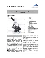
Brand: 3B SCIENTIFIC PHYSICS Pages: 12

1005438
Brand: 3B SCIENTIFIC PHYSICS Pages: 12

1005442
Brand: 3B SCIENTIFIC PHYSICS Pages: 12
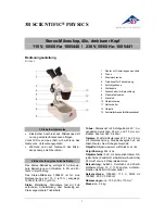
1005440
Brand: 3B SCIENTIFIC PHYSICS Pages: 12
1013152
Brand: 3B SCIENTIFIC PHYSICS Pages: 24

1013151
Brand: 3B SCIENTIFIC PHYSICS Pages: 24

1012404
Brand: 3B SCIENTIFIC PHYSICS Pages: 24

G-2030M
Brand: Galileo Pages: 2

AxioExaminer FTP-2100
Brand: Zeiss Pages: 12

86000
Brand: FINO Pages: 10

BX53-P
Brand: Olympus Pages: 36

CAMCOLMS1
Brand: Velleman Pages: 49

LSM800-2
Brand: Zeiss Pages: 6


