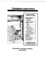
KitchenAid KULSL85, Installation Instructions Manual
The KitchenAid KULSL85 is a versatile and efficient appliance designed to elevate your cooking experience. With the Installation Instructions Manual available for free download at manualshive.com, users can effortlessly set up and optimize their kitchen space. This comprehensive manual provides step-by-step guidance for hassle-free installation and ensures a seamless integration into any culinary haven.
Share
Download


Reviews:
No comments
Related manuals for KULSL85

RI8260/47
Brand: Gaggia Milano Pages: 48

4B-2054N
Brand: OFFNOVA Pages: 10

213-7550
Brand: saro Pages: 24

Just Touch
Brand: TUR MIX Pages: 24

IGLICEND40SS
Brand: Igloo Pages: 30

WM-1011
Brand: Salton Pages: 9

LK-B20R
Brand: SEWOO Pages: 18

Dedica EC680
Brand: DèLonghi Pages: 9

DYMO XTL300
Brand: Newell Rubbermaid Pages: 16

EXP 4600
Brand: Orbegozo Pages: 25

EFE 1500
Brand: Smach Pages: 24

Firma INOVY MINI
Brand: LAVAZZA Pages: 111

CLR1215
Brand: U-Line Pages: 7

U-ADA15IMB-00A
Brand: U-Line Pages: 13
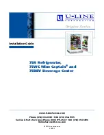
Origins 75BEV
Brand: U-Line Pages: 13

3018CLR SERIES
Brand: U-Line Pages: 13

ADA SERIES
Brand: U-Line Pages: 35

CG7212 selecta
Brand: UFESA Pages: 32


