Kenwood KVT-739DVD, Installation Manual
The Kenwood KVT-739DVD is a top-of-the-line car audio and video system that offers immersive entertainment on the go. Ensure a seamless installation with the detailed step-by-step instructions provided in the Installation Manual. Download this manual for free from manualshive.com and enjoy the ultimate audiovisual experience in your vehicle.
Share
Download


Reviews:
No comments
Related manuals for KVT-739DVD

Lectern
Brand: Da-Lite Pages: 8
SKU 4670PE31GDT
Brand: Diamond Multimedia Pages: 1

BS-210
Brand: Vivax Pages: 68

NVE-P1 - Navigation System Module
Brand: Alpine Pages: 37

VY-VZ
Brand: Commodore Pages: 18

AERCO AquaSolve AM8408-COM
Brand: Watts Pages: 8

TS
Brand: Conergy Pages: 36

Sound Pad S1
Brand: Hengbida Electronic Technology Pages: 19

ETV DVD 4549 LCD
Brand: AEG Pages: 70
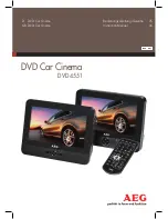
DVD 4551
Brand: AEG Pages: 66

DVD 4555 LCD
Brand: AEG Pages: 54

EC 4829
Brand: AEG Pages: 62

DVD 4533
Brand: AEG Pages: 65

MS6BK
Brand: Blaupunkt Pages: 97

MC200BT
Brand: Blaupunkt Pages: 112

Touring 500S
Brand: VMS Pages: 24

LBT-G200K
Brand: Sony Pages: 23

LBT-D550
Brand: Sony Pages: 23


