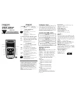
background image

Summary of Contents for TSTAT0713K

Page 1: ...1 For All TM Programmable D Temperature Humidity 2 T 2 MeetsResilential CaliforniaTitle24 MULTI STAGE PROGRAMMABLE International Comfort Products _2005 ...

Page 2: ...ATER _ AND AIR CONDITIONER BEFORE REMOVING THEOLD THERMOSTAT AND INSTALLINGTHENEWTHERMOSTAT WARNING International Comfort Products _ 2005 P N TSTAT0713K This device complies with Part 15 of the FCC rules Operation is subject to the following two conditions 1 This device may not cause harmful interference and 2 this device must accept any interference received including interference that may cause ...

Page 3: ...se steps call a qualified technician for assistance Assemble tools as shown below Flat Blade Wire cutter when not using Screwdriver Stripper j box _Make sure heater air conditioner your is working properly before beginning installation of the TSTAT0713K _ Carefully unpack the TSTAT0713K Save the screws wall anchors and instructions Page 2 ...

Page 4: ... does not come off easily check for screws Loosen the screws holding the thermostat base or subbase to the wall and lift away Disconnect the wires from the old thermostat Tape the ends of the wires as you disconnect them and mark them with the letter of the terminal for easy reconnection to the new thermostat Keep the old thermostat for reference purposes until your new thermostat is functioning p...

Page 5: ...he terminal designations on your old thermostat do not match those on the new TSTAT0713K refer to the chart below or the wiring diagrams that follow Install on the Function new TSTAT0713K terminal marked Fan Cooling Heating Power Common Rev Valve G Y1 W1 R C W1 0 B 2nd Stage Heat 2nd Stage Cool Humidifier Control Dehumidifier Control Comfort Alert Remote Sensor 5vdc Remote Sensor Signal Remote Sen...

Page 6: ...B_U_ i ERS_ i E Rsl E c E D O _j _I 18 gauge I I unshielded cable from the _r i th2mostat to the equipment I L _24v_c _ _ n L 24 vac return Optional wiring for dehumidification _ Ii 9 Fan relay Compressor relay _ 1st stage heat circuit i 0 HUMtorm n on HVAC unit if available tPages 8 19 20 and 24 of Owner s Manual Page 5 If using electric heat this option must be set to ON during Advanced Setup ...

Page 7: ..._ lmlY1 3 lill i HUM rr_ _ _ 18 g_uge I I unshielded cable from the ther __rmostat to the equipment IL _ __v_ _ n L 24 vac return Optional wiring for dehumidification _ I 9 Fan relay Compressor relay _ 1st stage heat circuit 2nd stage compressor relay _ DEHUM terminal _ on HVAC unit 3 if available If using electric heat this option must tPages 8 19 20 and 24 of Owner s Manual be set to ON during A...

Page 8: ...3 3 0 3 Y1 3 18 g_uge I I unshielded cable from the f_ 91 th2mostat to the equipment I L _ _Z4va_ _ n L_ 24 vac return LW____J Optional wiring for dehumidification _ 9 Fan relay Compressor relay _ 1st stage heat circuit 2nd stage Heat Circuit Relay _ DEHUM terminal _ on HVAC unit 3 if available If using electric heat this option must tPages 8 19 20 and 24 of Owner s Manual be set to ON during Adva...

Page 9: ...ng for dehumidification _ ID 3 0 3 Y1 3 3 18 g_uge I I unshielded cable from the 9 t2mostat to the equipment I v cc L _ 24 vac return m m L 9 Fan relay Compressor relay _ 1st stage heat circuit _ 2nd stage heat circuit relay 2nd stage compressor relay i DEHUM terminal on HVAC unit 3 if available tPages 8 19 20 and 24 of Owner s Manual Page 8 If using electric heat this option must be set to ON dur...

Page 10: ...3 3 3 0 3 _ lmlY1 3 lill i HUM _F_ CFLZ_ n 18 g_uge I I unshielded cable from the 9 th2mostat to the equipment I L _v_c _ _ n L 24 vac return Optional wiring for dehumidification _ I 9 _ Fan relay Compressor relay Reversing valve Fail to Heat _ I_ DEHUM terminal on HVAC unit 3 if available tPages 8 19 20 and 24 of Owner s Manual If using a Residential heat pump this option must be set to on during...

Page 11: ...ge I I unshielded cable from the ther __rmostat to the equipment I L _r _ 24vac n L _ 24 vac return 0 _ rqcrL jSJ 3 3 3 3 3 _ 3 Optional wiring for dehumidification _ 1 9 Fan relay Compressor relay D Reversing valve Fail to Heat 2nd stage compressor relay _ DEHUM terminal _ on HVAC unit 3 if available _Pages 8 19 20 and 24 of Owner s Manual If using a Residential heat pump this option must be set ...

Page 12: ...lill i HUM rr_ _ _ 18 g_uge I I unshielded cable from the 9 ther __rmostat to the equipment IL _ _Z4v_ _ _ n L 24 vac return Optional wiring for dehumidification _ I 9 Fan relay Compressor relay D Reversing valve Fail to Heat _ 2nd stage heat circuit relay _ DEHUM terminal _ on HVAC unit 3 if available tPages 8 19 20 and 24 of Owner s Manual If using a Residential heat pump this option must be set...

Page 13: ... should be set to OFF _ during Advanced Setup _ 3 0 3 Y1 3 18 g_uge I I unshielded cable from the 9 tLmostat to the equipment I v cc L _ 24 vac return m m L 9 Fan relay Compressor relay Reversing valve Fail to Heat _ 2nd stage heat circuit relay 2nd stage Compressor Relay DEHUM terminal u_ on HVAC unit if available If using a Residential heat pump Pages 8 19 20 and 24 of Owner s Manual this option...

Page 14: ...i E i E h iE 0 0 i c i c W2 i C Y2 i c ic i c i c i c Rsl i c GIlD i E iE C ilg 3 conductor 18 gauge unshielded cabte from I I the thermostat to the remote sensor _ i _ _1 i i i i i i SensorOpti nal Outdoor f 3 3 3 3 3 3 3 3 3 3 3 3 B 3 3 D Optional wiring for humidity system t E HUMIDIFIER tPages 5 8 22 and 24 of Owner s Manual Page 3 ...

Page 15: ...ess the UP DOWN buttons at the same time the display will change 3 Press the UP DOWN buttons at the same time again the current room temperature will be displayed 4 Use an accurate thermometer to measure room temperature Press the UP or DOWN buttons until the displayed temperature equals the room temperature 5 Press the MODE button the current humidity will be displayed 6 Use an accurate hygromete...

Page 16: ...rature The air conditioner should turn on NOTE Most equipment has a time delay of 5 minutes between cool cycles This feature is defeatable on the thermostat Consult the Owner s Manual under Setup cycles per hour Press the MODE button repeatedly until the HEAT icon appears on the display Press the UP or DOWN buttons until the set temperature is 10 degrees above room temperature The heating unit sho...

Page 17: ...Owner s Manual in the Setup section to defeat the cycles per hour and compressor timeguard _ YMPTOM The display is blank CAUSE Lack of proper power REMEDY Make sure power is turned on to the furnace and 24vac between R W If C is used 24vac between R C Humidity Control TSTAT0713K C US C _ _ Tested t p y I _with FCC Standards LISTED FOR HOME OR OFFICE USE 4Z95 P N 88 479 Rev 1 Page 16 ...

Reviews: