background image

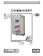
C O M B I V E R T

GB

Mat.No.

Rev.

00F50EM-KE03

1J

Installation Manual

Housing E

5.5…7.5 kW

230 V

4.0…15 kW

400 V

 The general 

EMC and safety 

directions at www.

keb.de have to be 

observed !

Summary of Contents for COMBIVERT F5 Series

Page 1: ...C O M B I V E R T GB Mat No Rev 00F50EM KE03 1J Installation Manual Housing E 5 5 7 5kW 230V 4 0 15kW 400V The general EMC and safety directions at www keb de have to be observed...

Page 2: ......

Page 3: ...GB 48 GB...

Page 4: ...nd trouble free ope ration Information Aide Tip Is used if a measure simplifies the handling or operation of the unit The information contained in the technical documentation as well as any user speci...

Page 5: ...e control terminal strip 19 3 6 Control board Multi Servo Application with encoder interface 20 3 6 1 X2A Control Terminal Strip 20 3 6 2 Connection of the control terminal strip 21 4 Operation of the...

Page 6: ...tion The drive converters shall be protected against excessive strains In particular no components must be bent or isolating distances altered in the course of transportation or handling No contact sh...

Page 7: ...150 6 8kHz 150 180 4 2kHz 150 180 A 8kHz 180 216 5 4kHz 150 180 B 16kHz 180 216 Input identification 1 3 phase 230VAC or DC supply 3 3 phase 400VAC or DC supply Housing type E Accessories 1 Braking tr...

Page 8: ...ains fuse type RK5 A 40 50 Max input fusing MMC type E A 40 45 1 The actual output frequency is depending on the parameterisation The output frequency is to be limited in such way that 1 10 of the swi...

Page 9: ...16 25 30 40 50 1 The actual output frequency is depending on the parameterisation The output frequency is to be limited in such way that 1 10 of the switching frequency is not exceeded Output frequen...

Page 10: ...5 F5 B with Operator X1A Connection for mains voltage motor braking resistor and temperature detection X2A Connection for control lines X4A Connection for operator or HSP5 service cable Connection for...

Page 11: ...t case no further measure at all e g at cyclic operation with down times up to the dissipation of the entire indicated heat loss at rated operation Always apply the shielding of motor and control cabl...

Page 12: ...section Tightening torque L1 W 0 2 6mm AWG 24 10 0 6Nm 5 lbinches T1 T2 0 1 2 5mm AWG 30 14 0 6Nm 5lbinches PE Screw M4 1 3Nm 11 5lbinches 3 3 2 Wiring instructions Absolutely observe the connecting...

Page 13: ...1 PE L2 L3 L3 L2 L1 PE DC connection 230V class DC connection 400 V class 250 370Vdc U PB T1 T2 N L2 V L3 W L1 PE 420 720Vdc U PB T1 T2 L2 V L3 W L1 PE This product can cause a d c current in the prot...

Page 14: ...stallation and Connection Terminals T1 T2 Tripping resistance 1 65 4k Reset resistance 0 75 1 65k Design in accordance with VDE0660 Part302 This function can be activated by the machine builder by sof...

Page 15: ...lation is switched off Regenerative operation is also secured by the internal fault disconnection The input must be programmed and inverted to external error Automatic restarting after cooling of the...

Page 16: ...in and output Programmable digital inputs 13 30VDC 0 smoothed Ri 2 1k scan time 2ms 10 Fixed frequency 1 CP 19 I1 I1 I2 fixed frequency 3 CP 21 11 Fixed frequency 2 CP 20 I2 14 Forward F Rotation sele...

Page 17: ...5mA max 30VDC 0 01 1A To avoid interferences a separate shielding must be provided for analog and digital control lines Depending on the use of the relay outputs an extra shielding is to be used too I...

Page 18: ...ction of fixed frequency I1 I2 fixed frequency 3 CP 21 11 Fixed frequency 2 CP 20 I2 12 External fault I3 Input for external error setting E EF 13 DC braking I4 Activates DC braking CP 22 23 14 Forwar...

Page 19: ...for analog and digital control lines Depending on the use of the relay outputs an extra shielding is to be used too In case of inductive load on the relay outputs a protective wiring must be provided...

Page 20: ...smoothed Ri 2 1k scan time 2ms 10 Fixed speed 1 CP 23 I1 Selection of fixed speeds I1 I2 fixed speed 3 no input analog set value 11 Fixed speed 2 CP 24 I2 12 External fault I3 Input for external erro...

Page 21: ...nly if a potential difference of 30V exists between the controls The internal resistance is red uced to 30k To avoid interferences a separate shielding must be provided for analog and digital control...

Page 22: ...it is always started with the last stored values or the factory setting 4 1 3 Interface operator part number 00F5060 2000 The interface operator corresponds to the functional range of the digital ope...

Page 23: ...alue of parameter CP 1 appears The function key changes between the parameter value and parameter number FUNC SPEED With UP and DOWN the value of the parameter number is increased decreased with chang...

Page 24: ...tered password the following modes are possible Display Mode CP_ro End customer menu CP Parameter read only CP_on End customer menu CP Parameter read write CP_SE Service menu like end customer menu bu...

Page 25: ...uf 1 CP 16 Rated frequency 0 400 0 0125 50 Hz uf 0 CP 17 Voltage stabilization 0 650 V off 1 0 V E uf 9 CP 18 Switching frequency 0 LTK 1 LTK E uf 11 CP 19 Fixed frequency 1 400 400 0 0125 5 Hz op 21...

Page 26: ...l CP 17 Voltage stabilization With this parameter a regulated output voltage in relation to the rated frequency can be adjusted For that reason voltage variations at the input as well as in the interm...

Page 27: ...P 26 12 means after reset and after auto reset UP Value Condition 0 Function off 1 at control release 2 at switch on 4 after reset 8 after Auto Reset UP CP 28 Response of external overtemperature CP 2...

Page 28: ...tput 1 function terminals X2A 24 26 CP 32 Relay output 2 function terminals X2A 27 29 The switching level of CP 31 is pre set to 100 00 The switching level of CP 32 is adjusted by CP 33 Va lue Functio...

Page 29: ...4 Inverter status switching level 45 Power stage temperature switching level 46 Motor temperature switching level 47 Ramp output value switching level 48 Apparent current CP 4 switching level 49 Forwa...

Page 30: ...erminal strip run stop X2A 14 and forward reverse X2A 15 the sign of the set point values have no effect on direction of rotation 6 Set value dependent positive value clockwise rotation negative value...

Page 31: ...CP 19 rated frequency 0 400 0 0125 50 Hz uf 00 CP 20 Encoder 1 inc r 1 65535 1 2500 Inc E ec 01 CP 21 Encoder 1 rotation 0 19 1 0 E ec 06 CP 22 Maximum speed 0 4000 0 125 2100 rpm op 10 CP 23 Step va...

Page 32: ...voltage e g USA with 460 V 3 Motor adaption for open loop operation with V f characteristic SMM When control release is active the adjustment was not completed nco appears in the display CP 21 Encoder...

Page 33: ...ng level 1 27 Real value CP 1 switching level 1 28 Setpoint CP 2 switching level 1 31 Absolute setpoint on AN1 switching level 1 32 Absolute setpoint on AN2 switching level 1 34 Setpoint at AN1 switch...

Page 34: ...ck stopping holding torque at speed 0 6 none No effect to the drive fault is ignored inapplicable CP 36 Reaction to external fault With the external error monitoring external units can take direct inf...

Page 35: ...ndent parameter 0 3 1 1 E fr 10 CP 20 Absolute position enc 1 0 65535 1 57057 ec 02 CP 21 Encoder 1 rotation 0 19 1 0 ec 06 CP 22 max reference forward 0 4000 0 125 2100 rpm op 10 CP 23 Step value 1 4...

Page 36: ...rting with the adjustment the direction of rotation must be checked The speed display at CP 1 must be positive when the engine runs manual in clockwise direction If that is not the case the direction...

Page 37: ...rning or error message after abnormal stopping 7 Overload pre warning 8 Overtemperature alert signal power stage 9 Ex overtemperature pre warning motor 11 Overtemperature pre warning OHI 20 Actual val...

Page 38: ...ck stop holding torque at speed 0 3 A PRx Immediate disabling of modulation Autoreset if no fault is present 4 A PRx Quick stopping disabling of modulation after reaching speed 0 5 A PRx Quick stop ho...

Page 39: ...ng to the following table Mains choke Uk 4 Example Inverter open loop 4 Closed loop inverter with mains and motor choke at non rigid supply system 400V mains voltage 15 340V motor voltage Inverter clo...

Page 40: ...king as dielectric fluid reacts with the acidic electrolyte and destroy themselves slowly This affects the dielectric strength and the capacity If the capacitor starts running with rated voltage it is...

Page 41: ...ions or delivered to a new storage A 5 Changing the response threshold of the braking transistor not valid for control type BASIC To prevent a premature switching of the brake transistor at input rate...

Page 42: ...Market the following instructions must be observed original text of the UL File 240V units Suitable For Use On A Circuit Capable Of Delivering Not More Than 10kA rms SymmetricalAmperes 240 Volts Maxi...

Page 43: ...CC J or RK5 shall be at least equal to the voltage of the Drivers Branch Circuit Protection Type E Self Protected Manual Motor Controllers for inverters F5 A housing Cat No Drive Input ating Self Prot...

Page 44: ...77V source only B 3 Additional Manuals You find supplementary manuals and instructions for the download under www keb de Service Downloads Downloads General instructions Part 1 EMC and safety instruct...

Page 45: ...GB 33 Notes...

Page 46: ...on 33 1 49620101 fax 33 1 45767495 net www keb fr mail info keb fr KEB UK Ltd Morris Close Park Farm Industrial Estate GB Wellingborough NN8 6 XF fon 44 1933 402220 fax 44 1933 400724 net www keb co u...

Reviews: