kansai R9000, Instruction Manual
The Kansai R9000 is a powerful and reliable tool designed to meet your industrial stitching needs. With its user-friendly interface and advanced features, this machine ensures precise and efficient results. Download the free Instruction Manual from manualshive.com to unlock the full potential of the Kansai R9000.
Share
Download


Reviews:
No comments
Related manuals for R9000

VX520
Brand: Republic Bank Pages: 18

Kenmore 385.12116690
Brand: Sears Pages: 93

43-3804
Brand: Radio Shack Pages: 36
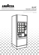
KLIX Series
Brand: LAVAZZA Pages: 32

Heavy Duty 1000
Brand: Janome Pages: 72

In-Sight 8000 Series
Brand: Cognex Pages: 116

43-3822
Brand: Radio Shack Pages: 20

WWE PRO 500-55G1-00
Brand: Stern Pinball Pages: 60

KM-590BL
Brand: SunStar Pages: 23

KX-PW720DLE6
Brand: Panasonic Pages: 24

FAX 4560
Brand: SAGEMCOM Pages: 72

AeroCut
Brand: UCHIDA Pages: 42

M17150-00
Brand: Minuteman Pages: 12

Ambassador C46000-00
Brand: Minuteman Pages: 12

E20 SPORT
Brand: Minuteman Pages: 40

2462
Brand: AT&T Pages: 50

3000
Brand: UnionSpecial Pages: 24

PF-P3100
Brand: Horizon Fitness Pages: 57


