

Getting Started Guide
CONNECTING THE DEVICE
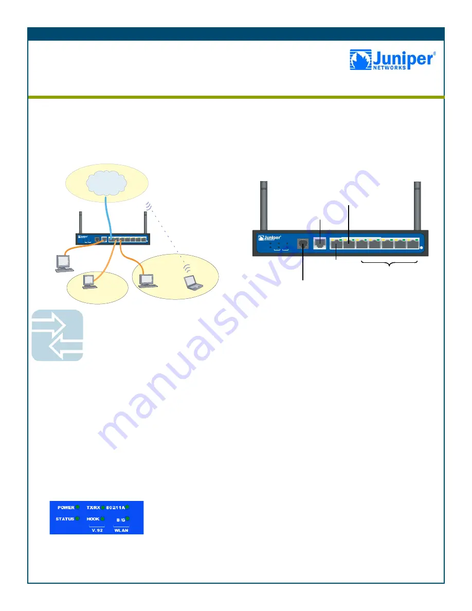
Use the network diagram above and the instructions below to connect and set up the
SSG 5 device to protect your network. Use the LEDs on the front panel of the device to
help you determine its status.
Step 1
Connect the workstation to the device using either of the following
methods:
•
Connect an Ethernet cable from one of the Trusted ports labeled
0/2 — 0/6 to the Ethernet port on the workstation.
(We recommend this connection method.)
•
Connect a straight-through serial cable from the console port to
the supplied DB-9 adapter which then connects to the serial port
on the workstation.
Step 2
Connect the device to a power source using the supplied power
cable. (We recommend using a surge protector.) Confirm that the
following LEDs are working correctly:
a.
Ensure that the POWER LED glows green. This indicates that the
device is receiving power.
b.
After the device starts (about 2 minutes), ensure that the STATUS
LED blinks green. This indicates that the device is operating
normally.
c.
Ensure that the Link Activity LEDs glow green for the connected
Ethernet ports. This indicates that the device has network
connectivity.
Step 3
Configure the workstation to access the device through a browser:
a.
Ensure that the workstation is properly connected to the device
using one of the methods presented in step 1.
b.
Change the TCP/IP settings of the workstation to automatically
obtain its IP address from the device using DHCP. For help, see
the operating system documentation for the workstation.
Note:
Ensure that your internal network does not already have a
DHCP server.
c.
If necessary, restart the workstation to enable the changes to
take effect.
You can use the Initial Configuration Wizard (ICW) to configure the
SSG 5 device. Before starting the ICW, decide how you want to
deploy your device. (For additional information, see the
SSG 5 Hardware Installation and Configuration Guide
.)
Getting Started
Use the instructions in this guide to help you connect your Secure Services Gateway (SSG) 5 device to
your network. For additional configuration information, see the
SSG 5 Hardware Installation and
Configuration Guide
. (This guide uses a version of the SSG 5-WLAN device to illustrate basic network
connectivity.)
SSG 5
V.92
STATUS
POWER
CONSOLE
TX /RX
CD
0
1
2
3
4
5
6
TX/RX
LINK
TX/RX
LINK
TX/RX
LINK
TX/RX
LINK
TX/RX
LINK
TX/RX
LINK
TX/RX
LINK
10/100
10/100
10/100
10/100
10/100
10/100
10/100
B /G
WLAN
V.92
802.11A
Callouts
Callouts
SSG 5
V.9 2
STATUS
POWER
CONSOL E
TX /RX
CD
0
1
2
3
4
5
6
TX/RX
LINK
TX/RX
LINK
TX/RX
LINK
TX/RX
LINK
TX/RX
LINK
TX/RX
LINK
TX/RX
LINK
10/100
10/100
10/100
10/100
10/100
10/100
10/100
B /G
WLAN
V.92
802.11A
Wireless0/0
Trust
Zone
Console
Untrust
Zone
Trust
(ethernet0/2 —
ethernet0/6)
DMZ
Zone
Console
DMZ
(ethernet0/1)
Untrust
(ethernet0/0)
AUX, V.92, or
ISDN
Secure Services Gateway 5


