background image

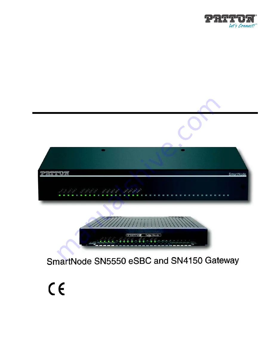
SmartNode SN5550 and SN4150

Enterprise Session Border Control-
ler, Integrated Access Device, and 
VoIP Gateway

User Manual

Sales Office:


+1 (301) 975-1000

Technical Support:


+1 (301) 975-1007

E-mail:


[email protected]

WWW:


www.patton.com

Part Number: 

07MDSN5550-SN4150-UM Rev. D

Revised: 

July 30, 2018

Important


This is a Class A device and is intended for use in a light industrial environment. It is 
not intended nor approved for use in an industrial or residential environment.

Summary of Contents for SmartNode SN4150

Page 1: ...e 1 301 975 1000 Technical Support 1 301 975 1007 E mail support patton com WWW www patton com Part Number 07MDSN5550 SN4150 UM Rev D Revised July 30 2018 Important This is a Class A device and is int...

Page 2: ...the terms of such license Patton Electronics warrants all SmartNode router components to be free from defects and will at our option repair or replace the product should it fail within one year from t...

Page 3: ...6 3 SmartNode Installation 30 4 Initial Configuration 38 5 Contacting Patton for Assistance 46 A Compliance Information 49 B Specifications 52 C Cabling 59 D Port pin outs 66 E SmartNode Device Factor...

Page 4: ...artNode SN4150 VoIP Gateway 28 3 SmartNode Installation 30 Planning the Installation 31 Site log 31 Network information 31 Network Diagram 31 IP related information 31 Software tools 32 Power source 3...

Page 5: ...ntacting Patton for Assistance 46 Introduction 47 Contact information 47 Contacting Patton Technical Services for Free Support 47 Warranty Service and Returned Merchandise Authorizations RMAs 47 Warra...

Page 6: ...nd AVA AVB models only 69 Fiber Ports F models only 69 E SmartNode Device Factory Configuration 70 Introduction 71 F Reset Button Functions 72 Introduction 73 Resetting the SmartNode device when it is...

Page 7: ...e to your laptop PC 39 12 Connecting the SmartNode to the network 41 13 Connecting the SmartNode to a laptop PC 42 14 Connecting SmartNode device and PC to a LAN with DHCP server 43 15 Typical Etherne...

Page 8: ...Configuration 40 8 Factory Default IP Address and Network Mask Configuration 43 9 WAN Interface Specifications 56 10 RJ 11 socket 62 11 RJ 45 male connector 65 12 10 100 Base T RJ 45 socket 67 13 1000...

Page 9: ...d a configuration Chapter 5 starting on page 46 contains information on contacting Patton technical support for assistance Appendix A starting on page 49 provides compliance info for the SmartNode dev...

Page 10: ...by the user The equipment shall be returned to Patton Electronics for repairs or repaired by qualified service personnel Mains Voltage In systems without a power switch line voltages are present in th...

Page 11: ...tlichen regulatorischen Anforderungen entsprechenden Schutzschalter abgesichert sein F r mit Wechselstrom betriebene Ger te muss sichergestellt sein dass das verwen dete Netzkabel alle g ltigen Normen...

Page 12: ...more leave at least 2 inches 5 cm to the left right front and rear of the SmartNode device for proper ventilation In accordance with the requirements of council directive 2002 96 EC on Waste of Electr...

Page 13: ...n font screen Terminal sessions and information the system displays are in screen font node The leading IP address or nodename of a SmartNode is substituted with node in boldface italic font SN The le...

Page 14: ...information Chapter contents SmartNode devices overview 16 SmartNode SN5550 eSBC 17 Port descriptions 19 Front panel LED definitions 20 SmartNode SN4150 VoIP Gateway 21 Port descriptions 23 Front pane...

Page 15: ...e SmartNode SN5550 eSBC and SN4150 VoIP Gateways are equipped with 2 ISDN BRI S0 T0 and 2 FXS ports some Models in addition have 2 FXO ports providing 4 G 722 G 711 or 4 T 38 calls simultane ously or...

Page 16: ...SN4150 SmartNode SN5550 eSBC The SmartNode SN5550 eSBC is a compact Enterprise Session Border Controller that supports 4 up to 8 voice calls FXS and BRI to VoIP and vice versa see figure 2 on page 18...

Page 17: ...n F stands for SFP slot being used for Fiber link termination EUI stands for external universal input power supply Note For a complete listing of available models refer to the SmartNode VoIP page at h...

Page 18: ...witched between TE and NT mode The inter face is internally terminated with 100 Ohm Point to point or point to multipoint configurable If the port is in NT mode a Phantom power sup ply can be switched...

Page 19: ...ew 20 SmartNode 5550 4150 Series User Manual 1 General information Figure 3 SmartNode SN5550 front panels Front panel LED definitions Figure 3 shows SmartNode SN5550 LEDs the LED definitions are liste...

Page 20: ...rtNode device is registered to a SIP server or a SIP device has registered to the SmartNode device Off indicates the unit is not configured or registered or has no active directly routed VoIP connecti...

Page 21: ...rtNode 5550 4150 Series User Manual 1 General information Note For a complete listing of available models refer to the SmartNode VoIP page at https www patton com products voip comparison asp S Figure...

Page 22: ...example FXS on hook voltage is 48V for each FXS port Analog voice ports FXO 0 0 FXO 0 3 FXO analog voice ports on RJ11 6 position 4 wire connectors These ports connect to FXS devices such as the PSTN...

Page 23: ...General information Front panel LED definitions Figure 5 shows SmartNode SN4150 LEDs the LED definitions are listed in table 5 on page 25 Figure 5 SmartNode SN4150 front panels Note If an error occurs...

Page 24: ...port is enabled Flashes when there are ongoing or ringing calls Off when no line or phone is connected or the port is shutdown Voice Ports FXO 0 FXO 3 In Idle state LED is off In Dialing or Ringing st...

Page 25: ...26 Chapter 2 Applications overview Chapter contents Introduction 27 Application for SmartNode SN5550 eSBC 27 Application for SmartNode SN4150 VoIP Gateway 28...

Page 26: ...eSBC The SmartNode SN5550 eSBC equipped with 2 Ethernet ports acts as an Enterprise Session Border Control ler securing the LAN from the WAN and it it available with a mix of Telephony interfaces incl...

Page 27: ...Optionally 2 or 4 FXO ports are available for Survivability or Telephone number porting use case see figure 7 Additionally SN4150 2ETH models have 2 Ethernet ports which enable them to be upgraded to...

Page 28: ...artNode 5550 4150 Series User Manual 2 Applications overview Legacy telephone to VoIP conversion Note Additional functions can be unlocked by loading software licenses such as an eSBC license bundle s...

Page 29: ...Installing the SmartNode device 32 Placing the SmartNode device 32 Connecting cables 33 Installation cable requirements for the WAN interface SN5550 2G 4G AVA AVB F Models 33 Connecting ISDN terminals...

Page 30: ...s should include information such as listed in table 6 Network information Network connection considerations that you should take into account for planning are described for several types of network i...

Page 31: ...imilar sturdy flat surface that offers easy access to cables Allow sufficient space at the rear of the chassis for cable connections Additionally you should consider the need to access the unit for fu...

Page 32: ...raight through RJ 45 cable to connect the WAN port For details on the G SHDSL port pinout refer to section G SHDSL EFM ATM port 2G and 4G mod els on page 68 For details on the VDSL and ADSL port pinou...

Page 33: ...0 4 0 6 and a terminal to the odd ports BRI 0 1 0 3 0 5 0 7 to benefit from the lifeline function See the full list of models on www patton com For details on the BRI port pin out and ISDN cables ref...

Page 34: ...back of the device Some Models have FXO ports as well with equal number of ports as for FXS The FXS interfaces are connected to ana log devices via cables see figure 10 on page 37 terminated with RJ...

Page 35: ...LL to ETH 0 0 2 Connect port ETH 0 1 to your LAN For details on the Ethernet port pin out and cables refer to Appendix C Cabling on page 59 and Appendix D Port pin outs on page 66 Connecting the power...

Page 36: ...tNode device 37 SmartNode 5550 4150 Series User Manual 3 SmartNode Installation Figure 10 Power LED Congratulations you have finished installing the SmartNode device Now go to Chapter 4 Initial Config...

Page 37: ...IP address 40 Factory default IP Settings 40 Login 40 Changing the WAN IP address 40 Connecting the SmartNode device to the network 41 Connecting the SN4150 to a laptop PC 42 Configure the Desired IP...

Page 38: ...ain power supply with the power cable Wait until the Power LED stops blinking and stays lit constantly Now the SmartNode device is ready Note The SmartNode device is equipped with Auto MDX Ethernet po...

Page 39: ...de start the Telnet application Type either the host name smartnode local or the default IP address into the address field of the Telnet application 192 168 1 1 Accessing your SmartNode via a Telnet s...

Page 40: ...he device when changing any configuration parameter 172 16 1 99 if ip WAN copy running config startup config 172 16 1 99 if ip WAN The SmartNode can now be connected to your network Connecting the Sma...

Page 41: ...blinking and stays lit constantly Now the SmartNode device is ready Note The SmartNode device has a fixed IP and a DHCP client setup to simplify configuration The Ethernet port is equipped with Auto...

Page 42: ...IP Settings The factory default configuration for the Ethernet interface is listed in table 7 The interface bound to ETH 0 0 WAN has a DHCP client running and a fixed IP address If these addresses ma...

Page 43: ...figure an IP interface 192 168 1 1 cfg context ip ROUTER 192 168 1 1 ctx ip ROUTER Now you can set your IP address and network mask for the interface ETH 0 0 WAN Within this example a network 172 16 1...

Page 44: ...nfigura tion templates you can manually configure the SmartNode instead of load ing a configuration file template In that case refer to the Trinity Command Line Reference Guide for information on conf...

Page 45: ...ntact information 47 Contacting Patton Technical Services for Free Support 47 Warranty Service and Returned Merchandise Authorizations RMAs 47 Warranty coverage 47 Out of warranty service 48 Returns f...

Page 46: ...ty program Note If you purchased your equipment from a Patton Electronics reseller ask your reseller how you should proceed with warranty service It is often more con venient for you to work with your...

Page 47: ...will be issued upon receipt and inspection of the equipment 30 to 60 days We will add a 20 restocking charge crediting your account with 80 of the purchase price Over 60 days Products will be accepte...

Page 48: ...9 Appendix A Compliance Information Chapter contents Compliance 50 EMC 50 Safety 50 Radio and TV interference 50 CE Declaration of Conformity 50 Authorized European Representative 50 ISDN Compliance 5...

Page 49: ...from the receiver re orienting the receiving antenna and or plugging the receiving equipment into a different AC outlet such that the computing equipment and receiver are on different branches CE Dec...

Page 50: ...he device is approved for connection to the public ISDN telecommunication network The interconnecting cables shall be acceptable for external use and shall be rated for the proper application with res...

Page 51: ...SP 53 Voice Connectivity 53 Data Connectivity 53 Voice Processing signaling dependent 53 Fax and modem support 54 Voice Signaling 54 Voice Routing session router 54 IP Services 55 WAN Interface if app...

Page 52: ...odel R option ISDN line power can be switched on per software per port 2 or 4 FXS ports RJ 11 12 2 or 4 FXO ports RJ 11 12 2 wire Loopstart EuroPOTS ETSI EG201188 Programmable AC impedance feeding rin...

Page 53: ...fax and modem detection Codec fallback for modem bypass T 38 Fax Relay Gr 3 Fax 9 6 k 14 4 K G 711 Fax Bypass incl Super G3 Fax Voice Signaling SIPv2 and SIPv2 over TLS licensed feature on SN4150 SIP...

Page 54: ...er Dual Stack Routing functionalities are included on SN5550 and optional on SN4150 BGP GRE RIP IPv4 and IPv6 Dual Stack OpenVPN License at additional charge Programmable static routes and policy rout...

Page 55: ...G SHDSL EFM 2G and 4G models Support ITU T G991 2 G 994 1 standards Support ITU T G 998 1 G bond TC PAM line modulation 16 32 64 128 CO or CPE Mode IEEE 802 3 2Base TL aka 802 3ah compliant Rate nego...

Page 56: ...069 config file and software image provisioning System Dual Core CPU Broadcom BCM53012 operating at 1GHz Memory 256 Mbytes DRAM 128 Mbytes Flash Physical Dimensions Plastic enclosure 7 3W x 1 6H x 6...

Page 57: ...e 5550 4150 Series User Manual B Specifications Weight Plastic enclosure 15 9 oz 450g Metal enclosure 25 6 oz 725 7 g Power Consumption 10W Operating Temperature 32 104 F 0 40 C Operating humidity up...

Page 58: ...59 Appendix C Cabling Chapter contents Introduction 60 Ethernet 60 Analog FXS 61 Analog FXO 63 ISDN BRI 64...

Page 59: ...r crossover cable to a host hubs switches PCs or other devices Note Connecting both Ethernet ports to the same switch will only work if the switch has a separate ARP table for each connection Figure 1...

Page 60: ...machines answering machines etc via cables terminated with RJ 11 connectors see section FXS port on page 67 for details on port pin outs Figure 17 Connecting an FXS device The Interconnecting cables s...

Page 61: ...Analog FXS 62 SmartNode 5550 4150 Series User Manual C Cabling Figure 18 RJ 11 pin out diagram Table 10 RJ 11 socket Pin Signal 3 Ring 4 Tip...

Page 62: ...nouts Note The phone line socket connector type and pinout available from the public network vary from country to country Refer to technical information avail able from your local operator for additio...

Page 63: ...ort of your NT or phones PBX Figure 20 Connecting an ISDN device The interconnecting cables shall be acceptable for external use an shall be rated for the proper application with respect to volt age c...

Page 64: ...ISDN BRI 65 SmartNode 5550 4150 Series User Manual C Cabling Figure 21 ISDN BRI RJ 45 pin out diagram Table 11 RJ 45 male connector Pin TE side signal NT side signal 3 Tx Rx 4 Rx Tx 5 Rx Tx 6 Tx Rx...

Page 65: ...outs Chapter contents Introduction 67 Ethernet 67 FXS port 67 FXO port 68 ISDN BRI NT Net or TE User ports 68 G SHDSL EFM ATM port 2G and 4G models 68 VDSL ADSL Port A and AVA AVB models only 69 Fiber...

Page 66: ...are not used FXS port The FXS ports use an RJ 11 connector with 6 positions The middle two positions 3 and 4 are used according to table 14 Note Pins not listed are not used Table 12 10 100 Base T RJ...

Page 67: ...d the user ports fallback together This enables you to place calls to the PSTN even if the unit is powered down Line power applied to the Line port is fed through to the Phone port at all times and in...

Page 68: ...ts sfpmodules asp Table 16 EFM Port Pin Signal Pair 1 Tip 1 2 Ring 1 3 Tip 2 4 Tip 0 5 Ring 0 6 Ring 2 7 Tip 3 8 Ring 3 DO NOT insert an RJ11 connector into an RJ45 socket An RJ11 connector which has...

Page 69: ...70 Appendix E SmartNode Device Factory Configuration Chapter contents Introduction 71...

Page 70: ...tion Factory configuration settings for the SmartNode device can be obtained with the following command through the CLI login admin password Enter 192 168 1 1 show config shipping config See Chapter 4...

Page 71: ...dix F Reset Button Functions Chapter contents Introduction 73 Resetting the SmartNode device when it is operating and the Power LED is lit 76 Resetting the SmartNode device when it is initially powere...

Page 72: ...page 76 Erase the startup config settings which is followed by a SmartNode device reboot as indicated by the slow blinking of all LEDs see section Resetting the SmartNode device when it is operating a...

Page 73: ...Introduction 74 SmartNode 5550 4150 Series User Manual F Reset Button Functions Figure 23 SN4150 Reset button...

Page 74: ...Introduction 75 SmartNode 5550 4150 Series User Manual F Reset Button Functions Figure 24 SN5551 Reset button...

Page 75: ...ceptions The following procedure must be performed starting with the SmartNode device in a powered off state 1 Hold the Reset button and 2 Apply power to the SmartNode device while continuing to hold...

Page 76: ...nds after the last Reset button press an action will be performed based on the selected pattern Table 19 Using the Reset button to switch to a backup image or erase flash memory LED Blink Pattern Acti...

Page 77: ...ent Chapter contents End User License Agreement 79 1 Definitions 79 2 Title 79 3 Term 79 4 Grant of License 79 5 Warranty 80 6 Termination 80 7 Notices 80 8 Other Licenses 80 9 Unenforceable Provision...

Page 78: ...software but are standard commercial software Except for the license use rights otherwise expressly provided in this Agreement no right title or interest in Patton Licensed Products is granted hereund...

Page 79: ...estroying all copies of the licensed Program s B Patton Electronics Company may terminate this Agreement should End User violate any of the provi sions of section 4 Grant of License on page 79 C Upon...

Page 80: ...reby irrevocably submits to the exclusive jurisdiction of the courts of the State of Maryland USA for any dispute arising under or relating to this agreement and waives user s right to institute legal...

Reviews: