


Doc. no 2.099.006.1.f 05/2023
Janitza electronics GmbH
Vor dem Polstück 6
D-35633 Lahnau
Support Tel. +49 6441 9642-22
Fax +49 6441 9642-30
Email: [email protected]
http://www.janitza.de
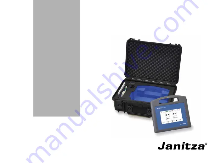
Mobile energy data collector
GridVis
®
Collector
User Manual (firmware 2.0.0 and higher)
www
.janitza.de
Summary of Contents for GridVis Collector
Page 25: ...25 www janitza de GridVis Collector...
Page 29: ...29 www janitza de GridVis Collector 270 mm 247 mm 91 mm Fig Housing of the GridVis Collector...
Page 37: ...37 www janitza de GridVis Collector...
Page 41: ...41 www janitza de GridVis Collector...
Page 45: ...45 www janitza de GridVis Collector...


