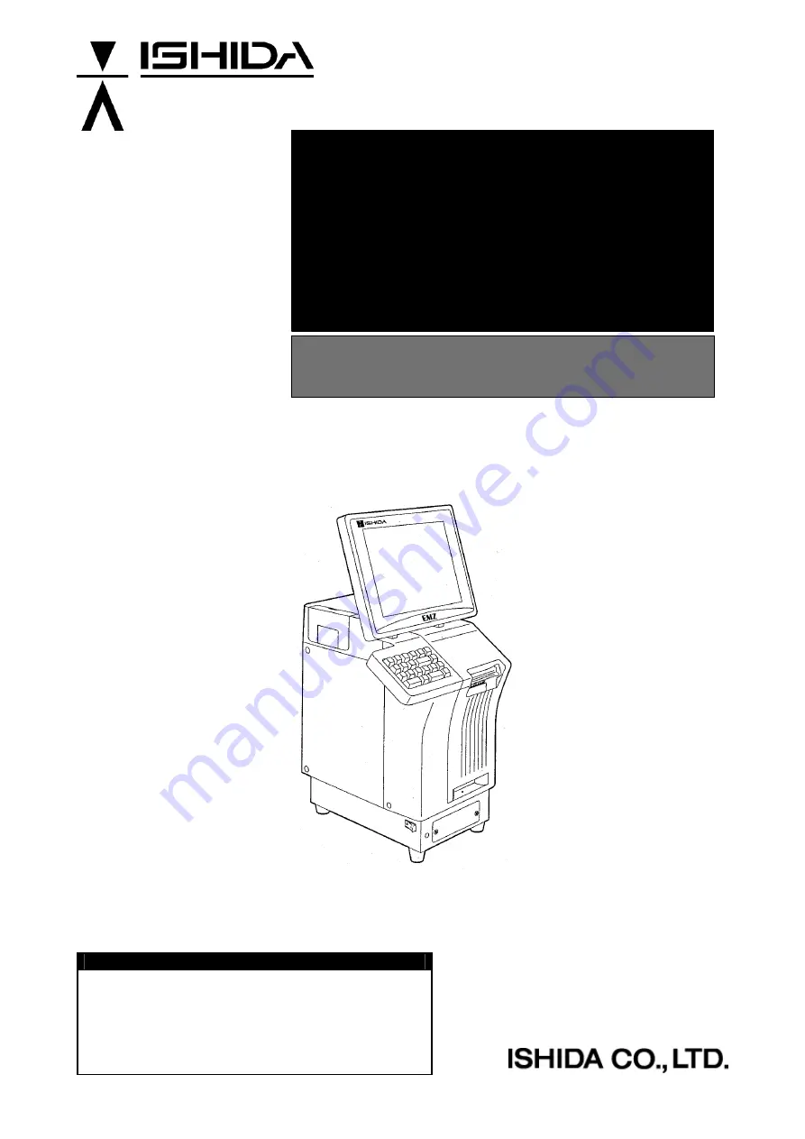
background image


IL-EMZ 

Service Manual 

COUNTRY: CAN. USA   2008.09.10 


IMPORTANT 

  Read this manual thoroughly, and do not perform 

installation, operation, maintenance, or inspection 
unless you fully understand all of the contents. 

  Keep this manual in a safe place where you can refer 

to it easily while installing, operating, and carrying out 
maintenance or inspections. 

Summary of Contents for IL-EMZ

Page 1: ...manual thoroughly and do not perform installation operation maintenance or inspection unless you fully understand all of the contents Keep this manual in a safe place where you can refer to it easily while installing operating and carrying out maintenance or inspections ...

Page 2: ...on may be reproduced stored in a retrieval system or transmitted in any form or by any means mechanical electronic photocopying recording or otherwise without prior written permission of ISHIDA The information contained in this manual is subject to change without notice ...

Page 3: ...ation inspection or maintenance procedure not specifically described in this manual or indicated on the machine itself CHANGE IN SPECIFICATIONS Machine specifications and accessories may be changed at any time due to improvements or other reasons Consult with your ISHIDA representative at any time to confirm the actual specifications of the purchased machine ERRORS AND OMISSIONS The information in...

Page 4: ...e instructions are for use by qualified service personnel who fully understand the potential hazards involved To avoid any possible danger do not perform any service procedures unless qualified to do so Perform only the specified service procedures To ensure personal safety do not perform any service procedures that are not specifically mentioned in this manual Avoid servicing while power is being...

Page 5: ...LOCATIONS 1 7 1 5 4 PRECAUTIONS FOR POWER SUPPLY 1 7 1 6 HARDWARE INSTALLATION 1 8 1 7 FINALIZING INSTALLATION 1 9 Chapter 2 SETUP MODE 2 1 ENTERING SETUP MENU 2 2 2 2 EXPIRY DATA SETTING 2 3 2 3 PASSWORD SETTING 2 5 2 4 REFERENCE DATA SETTING 2 6 2 5 TOTAL SETTING 2 8 2 6 PRESET REPORT SETTING 2 9 2 7 DATE FORMAT SETTING 2 11 2 8 KEY IMAGE SETTING 2 12 2 9 SYSTEM DATA SETTING 2 16 2 10 BARCODE SE...

Page 6: ...TE SETTING 3 26 Chapter 4 SYSTEM MODE 4 1 ENTERING SYSTEM SETTING MENU 4 2 4 2 SALES MODE SETTING 4 3 4 3 MACHINE NUMBER SETTING 4 4 4 4 HOLD DATA SETTING 4 6 4 5 AUTO PROGRAM SETTING 4 8 4 6 OPTION SETTING 4 10 4 7 CASSETTE SETTING 4 13 4 8 LABEL SPEC SETTING 4 16 4 9 LABEL FORMAT SETTING 4 21 4 10 PRINT SETTING 4 22 4 11 FILE CHECK SETTING 4 24 4 12 FILE SAVE AND LOAD 4 25 4 12 1 FILE DOWNLOAD 4...

Page 7: ...NECTOR JUNCTION PC BOARD P 918A 1 6 12 6 5 1 BOARD LOCATION 6 12 6 5 2 I O SIGNALS 6 12 6 6 LAN PC BOARD P 967 1 6 14 6 6 1 BOARD LOCATION 6 14 6 6 2 I O SIGNALS 6 14 6 7 DISPLAY JUNCTION PC BOARD P 919B 3 6 15 6 7 1 BOARD LOCATION 6 15 6 7 2 I O SIGNALS 6 15 6 8 SWITCHING POWER SUPPLY 2H113WI 6 17 6 8 1 BOARD LOCATION 6 17 6 8 2 I O SIGNALS 6 18 APPENDIX A LABEL FORMATTING A 1 LABEL FORMAT TABLE ...

Page 8: ...vi IL EMZ Service Manual memo ...

Page 9: ...ice Manual 1 1 Contents 1 1 SPECIFICATIONS 2 1 2 NAME OF EACH PART 4 1 3 OUTER DIMENSIONS 5 1 4 PREPARATION FOR INSATALLATION 6 1 5 PRECAUTIONS FOR INSTALLATION 7 1 6 HARDWARE INSTALLATION 8 1 7 FINALIZING INSTALLATION 9 INSTALLATION 1 ...

Page 10: ...m storage medium 14 1 Flash ROM 1MB Boot program 14 2 Compact Flash 32MB OS Application program 15 Memory capacity The registration number varies depending on the total memory capacity 15 1 PLU master 511 characters 4 000 PLUs 5 prices 15 2 Additive master 511 characters 9 999 additives 15 3 POP master 39 characters 999 POPs 15 4 Comment master 511 characters 99 comments 15 5 Origin master 39 char...

Page 11: ...git code including check price 6 digit code including flag 5 digit code including check price 6 digit code 5 digit price 19 Durability 19 1 Number of label issues 16 2 million labels label length 42mm 9 000 labels 360 operation days 5 years 721km 19 2 Printer frame drawer 7 300 times 4 times day 360 days 5 years 19 3 Display angle adjustment frequency 3 650 times 2 times day 360 days 5 years 19 4 ...

Page 12: ...4 IL EMZ Service Manual 1 2 NAME OF EACH PART 1 2 1 FRONT VIEW Touch panel Stroke keys Power switch Label outlet Label cassette Brightness adjustment dial Lighter Darker 1 2 2 REAR VIEW Rear Connectors Located in the rear cover ...

Page 13: ...Chapter 1 INSTALLATION IL EMZ Service Manual 1 5 1 3 OUTER DIMENSIONS Unit mm ...

Page 14: ...acked Main body Scale unit Grounding cable Tool Plus Screw driver User s manual Cleaning pen NOTE Parts are fixed with adhesive tapes so as not to move when transported Remove these tapes when unpacking 1 4 2 THINGS TO BE PREPARED IF 21FD 3 5 inch 2DD floppy disk in which the user s data is recorded I2NET cable D sub 9 pin modular Labels ...

Page 15: ...leave screws or other foreign objects in the machine after performing routine maintenance since this can cause major damage to the machine when the electrical switch is turned on Always remove wires by holding the connector and pulling to disconnect Do not disconnect by pulling on the wires themselves since this may cause a wire to snap or damage the connection Before disassembling or adjusting th...

Page 16: ...ct them according to the following Other machine of the master satellite system I2NET INLINE Dsub 9 pin Optional printer I2NET OPTION1 Modular jack IF 21FD I2NET INLINE Dsub 9 pin Journal printer RS 232C 5 Fix the harnesses NOTE Nylon clamps to fix harnesses are not attached Prepare the nylon clamps beforehand with their sizes according to the number of the connected harnesses Fig 1 Rear Connector...

Page 17: ...ATION Call up a product place a load on the weighing platter and issue a label After issuing the label clear the result Connect the IF 21FD and save the settings Explain the operation method and precautions to the user Operation check Set content save Operation explanation ...

Page 18: ...Chapter 1 INSTALLATION 1 10 IL EMZ Service Manual memo ...

Page 19: ...data Setting 6 2 5 Total Setting 8 2 6 Preset report Setting 9 2 7 DATE FORMAT SETTING 11 2 8 Key image setting 12 2 9 System data setting 16 2 10 Barcode setting 20 2 11 Item code setting 22 2 12 PLU update setting 23 2 13 SERIAL No setting 26 2 14 BATCH PRINT SETUP setting 27 2 15 Memory i o setting 28 2 16 Default data setting 31 SETUP MODE 2 ...

Page 20: ...hat the Main Menu screen is displayed Then touch the SETUP button on the screen 2 The Setup Menu screen appears To display the next page enter 9 9 9 using numeric keys on the operation panel and touch the PAGE button on the screen Ä 3 The second page of the Setup Menu screen appears ...

Page 21: ... screen Note This function does not use In the case of 6 or more characters of the date title The title of the date is using the UNIT TYPE FIXED Character of a label format 2 The Expiry Date Setting screen appears 3 Enter the number of days for Conversion Days using numeric keys on the operation panel and touch the SET button on the screen EXAMPLE 3 days 3 ...

Page 22: ...screen EXAMPLE Select Best Before 5 The text editing screen appears Edit the text by referring to the procedure described in appendix Text Editing A maximum of 6 characters can be inputted EXAMPLE Change to Sell 6 After editing the text touch the SET and RETURN buttons 7 The confirmation screen appears Then touch the EXECUTE button to save the data 1 2 1 2 ...

Page 23: ...SWORD SET button on the screen 2 The Password Setup screen appears 3 Enter a 6 digit numeric data and touch the SET button in a desired field EXAMPLE Password 123456 Then touch the SET button And touch The mode button Note To disable a password enter 000000 and touch the SET button When you have forgotten the password 1 2 3 4 5 6 ...

Page 24: ... to print a sell by date SHELF LIFE Enter a numeric value and touch this field USE BY DATE PRINT Touch to select whether or not to print a use by date USE BY DATE Enter a numeric value and touch this field PACK TIME PRINT Touch to select whether or not to print a pack time PACK TIME FLAG Touch to select of using the clock time or designated time SB TIME PRINT Touch to select whether or not to prin...

Page 25: ... 1 Enter a desired logo number and touch this field LOGO 2 Enter a desired logo number and touch this field LOGO 3 Enter a desired logo number and touch this field ZERO PRICE PRINT Touch to select whether to use zero price print function or not YES Only a buzzer sounds print 0 00 or blank NO An error screen pops up printout does not carry out Barcode print at Zero Price Zero Price Print functions ...

Page 26: ...uch to select whether to add to Weekly Total or not CUMULATIVE TOTAL Touch to select whether to add to Cumulative Total or not PERIOD TOTAL Touch to select whether to add to Period Total or not CR AUTO MODE PRODUCTION TOTAL Touch to select whether to add to Cash Register Auto Mode Production Total or not DAILY TOTAL CSTM UNIT PRICE ZONE Enter a numeric data and touch the corresponding field DAILY ...

Page 27: ...uch the PRESET REPORTS button on the screen 2 The Preset Report screen appears Then select a preset report for daily totals or total by touching the corresponding button Touch to select all reports Touch to select each report Touch to page down Touch to move down the selection Touch to move up the selection Touch to page up ...

Page 28: ...Chapter 2 SETUP MENU 2 10 IL EMZ Service Manual 3 Touch to select a desired field for enabling or disabling the report printing EXAMPLE Print Daily Grand Total Sales Repeat this step for more selections ...

Page 29: ...TTING This function is the date format shown on the main display 1 Ensure that the Setup Menu screen is displayed Touch the DATRE FMT SET button on the screen 2 Select the Date format Then touch to select the MM DD YYY or DD MM YYY by touching the corresponding button ...

Page 30: ...ation Save the bitmapped image into the Compact Flash card Reference bit map size 640x480 pixels Insert the Compact Flash card in Compact Flash card adapter Then insert the Compact Flash card adapter into the CF 2 2 Ensure that the Setup Menu screen is displayed Touch the KEY IMAGE button on the screen 3 The Image Select screen appears Compact Flash card adapter is required ...

Page 31: ...mage area and touch the EXEC button to paste on the desired preset key 5 The Key Image screen appears Adjust the image by using this screen Select the key size to be used LAYOUT S M L 6 Adjustment the image SAIZ 10 341 Trimming position Touch and drag Touch the position button 2 1 ...

Page 32: ...button once again 8 Save to the memory of IL EMZ Number the key image Input the number and touch the SAVE button Key image is saved on CF card of a program IMGSV001 BMP Cautions The same number is overwritten 9 The method of programming Touch the PRESET KEYS of a Program menu MODE PRESET SET KEY KIND IMAGE 1 2 3 4 ...

Page 33: ...Chapter 2 SETUP MENU IL EMZ Service Manual 2 15 Input the Key image number and touch the PRESET button 5 Operation mode Screen Program menu Preset Keys Screen ...

Page 34: ...Setup Menu screen is displayed To display the next page enter 9 9 9 using numeric keys on the operation panel and touch the PAGE button on the screen Ä 2 The second page of the Setup Menu screen appears Then touch the SYS DATA SET button on the screen 3 The System Data Setting screen appears ...

Page 35: ...PRICE PRINT Touch to select whether or not to print a fixed price RECEIPT SUBTOTAL DISCOUNT KIND Touch to select a desired subtotal discount type POS CODE ERROR Touch to select a desired error display type ITEM COUNT SELECT Touch to select a desired item counting method CR PLUADDMODE NON INPAD LABEL PRINT Cash register Price lookup Select the label issue when not inputting the amount of money FRON...

Page 36: ...ON PERMIT is selected on line switching is prohibited in the normal mode RESULT CSV SEND ERROR SELECT Touch to select a desired field When SAVE RESULT is selected the file name of the result file can be changed or stored during error sending RESULT CSV STORAGE FILE SELECT Touch to select a desired field When RESULT HEAD DATE is selected the head data can be saved in CSV file When SYSTEM DATE is se...

Page 37: ... calculation type Shelf life value 1 day today Shelf life value 1 day tomorrow UNIT PRICE KEY Touch to select whether to enable this key or not FIXED PRICE KEY Touch to select whether to enable this key or not MARK DOWN KEY Touch to select whether to enable this key or not WEIGHT KEY Touch to select whether to enable this key or not STORE NUMBER KEY Touch to select whether to enable this key or no...

Page 38: ...he Setup Menu screen is displayed To display the next page enter 9 9 9 using numeric keys on the operation panel and touch the PAGE button on the screen Ä 2 The second page of the Setup Menu screen appears Then touch the BARCODE SET button on the screen 3 The Barcode Set screen appears ...

Page 39: ...tton to specify the POS flag Select the OCR type Normal or UCC DEFAULT POS CODE TYPE Select a desired default POS code type by touching the corresponding filed UPC FORMAT Touch this field to display the UPC format table for selecting a desired format RSS Exp Format Touch this field to display the RSS Expansion format table for selecting a desired format ...

Page 40: ...operation panel and touch the PAGE button on the screen Ä 2 The second page of the Setup Menu screen appears Then touch the ITEM CODE button on the screen 3 The Product Code Setting screen appears CODE SELECTION Touch to select the code type and set the code digits by touching desired fields JAN CODE Touch to select JAN 8 or JAN 13 and set the code digits by touching desired fields ...

Page 41: ...d touch the PAGE button on the screen Ä 2 The second page of the Setup Menu screen appears Then touch the PLU UPDATE button on the screen 3 The PLU Update screen appears Touch to select each item Touch to page down Touch to move down the selection Touch to move up the selection Touch to page up After selecting items touch this button for execution After selecting items touch this button for execut...

Page 42: ... to NON WEIGH 5 Touch the SELECT button The related fields will be highlighted 6 To change data enter a numeric value and touch a desired field EXAMPLE Change to 3 50 7 Touch to select a desired field and touch to change a selection EXAMPLE Select Markdown Flag and change to SPECIAL 1 2 3 5 0 ...

Page 43: ...on The related fields will be highlighted 9 Touch to select a desired field and enter a desired numeric value EXAMPLE Change to 2 90 10 Touch the SELECT EXECUTE or EXECUTE ALL button 11 The confirmation screen appears Then touch the EXECUTE or EXECUTE ALL button 1 2 0 9 2 ...

Page 44: ...xt page enter 9 9 9 using numeric keys on the operation panel and touch the PAGE button on the screen Ä 2 The second page of the Setup Menu screen appears Then touch the SERIAL No button on the screen 3 The Serial No screen appears SERIAL NO START N You can set up serial number within 4digits COUNT SET Select the up button or down button ...

Page 45: ... display the next page enter 9 9 9 using numeric keys on the operation panel and touch the PAGE button on the screen Ä 2 The second page of the Setup Menu screen appears Then touch the BATCH PR SET button on the screen 3 The Batch Print set up screen appears BATCH PRINT ORDER Labels can print in the order entered or reverse order ...

Page 46: ... Setup Menu screen is displayed To display the next page enter 9 9 9 using numeric keys on the operation panel and touch the PAGE button on the screen Ä 2 The second page of the Setup Menu screen appears Then touch the MEMORY I O button on the screen 3 The Memory card in out screen appears ...

Page 47: ... the Main button As for a file name RESULT FILE is then chosen automatically 2 Touch the RESULT FILE button 3 Touch the EXE button Screen A appears Then touch the EXECUTE button 5 This function is transmits to main memory from the memory card 1 Touch the Main button The file name which can be transmits appears 1 2 3 4 1 ...

Page 48: ...Chapter 2 SETUP MENU 2 30 IL EMZ Service Manual 2 Touch the file name to transmit 3 Touch the EXE button Screen A appears Then touch the EXECUTE button 2 2 3 4 ...

Page 49: ...w PLU is created 1 Ensure that the Setup Menu screen is displayed To display the next page enter 9 9 9 using numeric keys on the operation panel and touch the PAGE button on the screen Ä 2 The second page of the Setup Menu screen appears Then touch the DEFAULT DATA button on the screen 3 The Default PLU Data Setting screen appears ...

Page 50: ...BY DAYS Enter the number of days for the use by date and touch this field BARCODE TYPE Touch this field to display a pop up screen for selection BARCODE FORMAT Touch this field to display a pop up screen for selection POS FLAG Enter a flag number and touch this field BARCODE Enter a barcode and touch this field OPEN PRICE Touch this field to display a pop up screen for selection 0 refer 1 prohibit...

Page 51: ...reen for selection DEPARTMENT Enter a department number and touch this field GROUP Enter a group number and touch this field ITEM CODE Enter an item code and touch this field UNIT TYPE Touch this field to display a pop up screen for selection 0 refer 1 oz 2 ib 3 kg 4 g 5 pc 6 box 7 bundle 8 pack 9 cut 10 slice 11 cup 12 pkt 13 bag 14 bunch 15 bottle 16 LB 17 no prn COST PRICE Enter a cost price an...

Page 52: ...Chapter 2 SETUP MENU 2 34 IL EMZ Service Manual ...

Page 53: ...g Test menu 2 3 2 KEY CHECK 3 3 3 Self Diagnostic 7 3 4 Memory Clear 9 3 5 Display Confirmation 10 3 6 Printer Adjustment 12 3 7 Program Number 20 3 8 Communication Check 21 3 9 Option Check 22 3 10 Memory Data modification 23 3 11 Time and date setting 26 TEST MODE 3 ...

Page 54: ... EMZ Service Manual 3 1 ENTERING TEST MENU 1 Ensure that the Main Menu screen is displayed 2 Enter 4 9 5 3 4 4 using numeric keys on the operation panel and touch the TEST MODE button on the screen 3 The Test Menu screen appears ...

Page 55: ...Chapter 3 TEST MENU IL EMZ Service Manual 3 3 3 2 KEY CHECK 1 Ensure that the Test Menu screen is displayed Then touch the KEY CHECK button on the screen 2 The Key Check Menu screen appears ...

Page 56: ...heck Menu screen is displayed Then touch the NUMBER KEY CHECK button on the screen 2 The Number Key Check screen appears 3 To check that each key on the operation panel is operating properly press any desired keys on the operation panel and check that the corresponding key turns black in color ...

Page 57: ...EL ADJUSTMENT 1 Ensure that the Key Check Menu screen is displayed Then touch the TOUCH PANEL ADJUST button on the screen 2 The Touch Panel Adjustment screen appears 3 Touch the center of the upper left button on the screen The touched button turns black in color ...

Page 58: ...ual 4 Touch the center of the bottom right button on the screen The touched button turns black in color 5 Touch the center of the small upper right button on the screen for acknowledgement You can hear the beep when the adjustment is completed ...

Page 59: ...ory Note that all memories will be initialized when this menu is used 1 Ensure that the Test Menu screen is displayed Then touch the SELF DIAGNOSTIC button on the screen 2 The Self Diagnostic screen appears Touch the EXECUTE button on the screen As a checking result the word NORMAL or ABNORMAL appears in each field ...

Page 60: ...D SUB hardware check Check cable is required y Defect of P 910 y Defect of P 907 y Defect of harness C2 RS 232C 63 8459 20 CARDSLOT UPPER CHECK PCMCIA upper hardware check Check cable is required y Defect of P 910 CARDSLOT LOWER CHECK PCMCIA lower hardware check Check cable is required y Defect of P 910 I2 NET ELAN SELFCHECK I2 NET ELAN hardware check y Defect of P 910 I2 NET ILAN SELFCHECK I2 NET...

Page 61: ... is displayed Then touch the MEMORY CLEAR button on the screen 2 Touch one of the CLEAR INITIALIZE and SET buttons on the screen SRAM CLEAR Master data in SRAM is cleared except system master data SYSTEM DATA INITIALIZATION System master data returns to initial values TEST DATA SET Test data is set ...

Page 62: ... 5 DISPLAY CONFIRMATION 1 Ensure that the Test Menu screen is displayed Then touch the DISPLAY CHECK button on the screen 2 The vertical color pattern screen appears Check brightness of the screen 3 Touch the HORIZONTAL VERTICAL button on the screen ...

Page 63: ...Chapter 3 TEST MENU IL EMZ Service Manual 3 11 4 The horizontal color pattern screen appears Check brightness of the screen ...

Page 64: ...ing methods Method 1 Touch the SET button to automatically read the thermal head resistance value and store it in the memory of the main body Method 2 Touch the SET button after a numeric data entry to manually set the resistance value HEAD TYPE Enter 0 1 or 2 and touch the SET button to select a type of thermal head type being used 0 LH4114 1 LH4116 2 BHP4312 PRINTER USAGE DISTANCE Enter a numeri...

Page 65: ...t used LABEL SENSOR LEVEL Displays label sensor level Press this button to finely adjust the label sensor level display field will change to green and press the UV adjustment buttons Press this button again to change the display to white and set adjustment data The level range is 0 255 PEEL SENSOR LEVEL Displays peel sensor level Touch this button to finely adjust the peel sensor level display fie...

Page 66: ... MENU 3 14 IL EMZ Service Manual DPM DIGITAL POTENTIAL METER Digital The position of volume can be checked It is a minimum 0 from a maximum 255 The following figure is a case where it transposed to analog type volume ...

Page 67: ...en a sensor level is 60 or more Threshold Detection mode When the value of Label sensor DPM System Setting menu Label Specification is 1 or more it is the mode of Threshold Detection The label gap is detected when a sensor level is exceeded threshold The value of a threshold is displayed on the Label gap initial And the value can be changed The standard label is the mode of Level Detection The Lab...

Page 68: ...ld will change to green Touch the UV adjustment buttons Touch this button again to change the display to white and set adjustment data 2 The check method of a sensor level Touch the FEED key 2 or 3 times Then label comes out Enter the 2000 at numeric keys and press the X key Then graph pops up FEED Label gap 2 0 0 0 X Label gap ...

Page 69: ...or more Then the level of the gap also becomes small Adjustment is completion if the gap level is about 100 or more between label gap level from label portion level It sets threshold Mode In not fulfilling the above mentioned conditions and case of 60 or more output at Label portion Adjustment of Threshold Detection mode can be performed in system setting mode 200 240 Label portion Level 40 Level ...

Page 70: ...em Setting menu Touch a button in the following procedure System Setting menu LABEL SPEC 9 9 9 PAGE 3 Enter the value of LABEL SENSOR DPM at numeric keys and touch the Label sensor DPM field 4 Enter the temporary threshold value 120 at numeric keys and touch the Label sensor DPM field 5 Press the FEED key 2 or 3 times Then label comes out Enter the 2000 at numeric keys and touch the X key Then gra...

Page 71: ...ion of No 4 Enter the Threshold Preset value at numeric keys and press the Label sensor DPM field XXX Threshold Preset value A 2 3 1 2 A is the value between label detection part and label gap detection part Label detection part is the highest value Label gap detection part is the lowest value Preset value is between one half of A and 2 3 ...

Page 72: ... 3 TEST MENU 3 20 IL EMZ Service Manual 3 7 PROGRAM NUMBER 1 Ensure that the Test Menu screen is displayed Then touch the PROGRAM No button on the screen 2 Confirm Each software program and the version number ...

Page 73: ...f P 918 connecter junction ELAN RAM test Communication buffer read write test yDefect of P 910 main board ELAN cable test 1 Main body Æ IF 21FD communication test y The poor cable between IL EMZ and IF 21FD ILAN loop back test Driver Æ Receiver communication test yDefect of P 910 main board y Defect of P 918 connecter junction ILAN RAM test Communication buffer read write test yDefect of P 910 mai...

Page 74: ... screen appears Connect the scanner for reading the barcode The scanned data is displayed in the Scanner Read Data field 3 Slot 1 Check Insert a CF card into the slot 1 and touch the EXECUTE button on the screen Slot 2 Check Insert a CF card into the slot 2 and touch the EXECUTE button on the screen Drawer Open Check Connect a drawer and touch the EXECUTE key to open the drawer ...

Page 75: ...memory data or the machine will not operate normally 1 Ensure that the Test Menu screen is displayed Then touch the MEMORY DATA MODIFY button on the screen 2 The Memory Data screen appears Touch the SRAM DATA MODIFY button to confirm SRAM data 3 The HEX data appears on the SRAM Data Modify screen ...

Page 76: ... button on the screen to display ASC data on the SRAM Data Modify screen 5 Touch the MENU button on the screen to return to the Memory Data screen 6 Touch the F ROMDATAREFERENCE button to confirm F ROM data 7 The HEX data appears on the F ROM Data Reference screen ...

Page 77: ...Chapter 3 TEST MENU IL EMZ Service Manual 3 25 8 Touch the ASC button on the screen to display ASC data on the F ROM Data Reference screen ...

Page 78: ...e that the Test Menu screen is displayed Then touch the TIME DATESETTING button on the screen 2 The Time And Date Setting screen appears 3 To change the date enter the current date using numeric keys on the operation panel and touch the DATE field EXAMPLE SEP 05 2008 0 9 0 4 2 0 0 8 ...

Page 79: ...Chapter 3 TEST MENU IL EMZ Service Manual 3 27 4 To change the time enter the current time using numeric keys on the operation panel and touch the TIME field EXAMPLE 19 25 00 1 9 2 5 0 0 ...

Page 80: ...Chapter 3 TEST MENU 3 28 IL EMZ Service Manual memo ...

Page 81: ...Mode setting 3 4 3 Machine Number setting 4 4 4 Hold Data setting 6 4 5 Auto Program setting 8 4 6 Option Setting 10 4 7 Cassette Setting 13 4 8 Label Spec setting 16 4 9 Label Format setting 21 4 10 Print Setting 22 4 11 File check setting 24 4 12 File Save and Load 25 4 13 Free master setting 33 SYSTEM MODE 4 ...

Page 82: ...EMZ Service Manual 4 1 ENTERING SYSTEM SETTING MENU 1 Ensure that the Main Menu screen is displayed 2 To enter System Setting Men enter 4 9 5 3 4 4 and press the PLU key on the operating console Ä 3 The System Setting Menu screen appears 3 ...

Page 83: ...en 2 The Sales Mode Setting screen appears Touch to select whether or not to use an operator system When program was exchanged Neither is select Follow a message in a setup at this case With operator When operator analysis is conducted at total It is necessary to make a operators button 3 The No of Label Display screen appears Touch to select whether or not to use a label display ...

Page 84: ...er Setting screen appears MACHINE NO Enter a machine number and touch the SET button DEPARTMENT NO Enter a department number and touch the SET button EQUIPMENT SETTING Touch to select one among following three types yStandalone machine ySatellite machine yMaster machine COMMUNICATION MODE Touch to select either Offline or Online CSIS COMMUNICATION SPEED Touch to select either Standard speed or Hig...

Page 85: ...Chapter 4 SYSTEM SETTING MENU IL EMZ Service Manual 4 5 ...

Page 86: ...MZ Service Manual 4 4 HOLD DATA SETTING This function is used only for Cash Register application 1 Ensure that the System Setting Menu screen is displayed Then touch the HOLD DATA button on the screen 2 The Hold Data Setting screen appears ...

Page 87: ...her YES or NO No Label issuing condition either peeled off or with backing paper is not hold Yes Label issuing condition either peeled off or with backing paper is hold PLU HOLD Touch to select either YES or NONE None The PLU name is not hold after the print ends Yes The PLU name is hold for the called PLU after the print ends SHOP HOLD Touch to select either YES or NO No The Shop name is not hold...

Page 88: ...RAM button on the screen 2 The Auto PLU Update screen appears Then touch to select either YES or NO for each item No The data which is temporarily changed in the operation mode is not reflected in the PLU master Yes The PLU master is updated automatically with the data temporarily changed in the operation mode Note When the RAM is cleared everything is set to No ...

Page 89: ...Chapter 4 SYSTEM SETTING MENU IL EMZ Service Manual 4 9 ...

Page 90: ... Service Manual 4 6 OPTION SETTING 1 Ensure that the System Setting Menu screen is displayed Then touch the OPTION SET button on the screen 2 The Option Setting screen appears Then touch to select a desired field for each item on the screen 2 ...

Page 91: ...e confirmation screen The machine is automatically turned OFF and turned ON again to apply parameter table settings PING Touch to execute a communication test with the host computer LOWER LETTER UPPER LETTER Touch to select upper or lower case letters for character entry Character buttons A B C etc Touch to enter characters for setup values INPUT Displays the data input from the numeric keys and o...

Page 92: ...ameters Delete a parameter by pressing the corresponding field on the screen without numeric entry to display the confirmation screen and touch the EXECUTE button on the confirmation screen EXECUTE Execute processing CANCEL Cancels execution 5 To turn the page touch the PAGE button on the screen Then touch to select a desired field for each item on the screen ...

Page 93: ...Service Manual 4 13 4 7 CASSETTE SETTING Up to 7 cassettes 1 7 are available with this machine 1 Ensure that the System Setting Menu screen is displayed Then touch the CASSETTE SET button on the screen 2 The Cassette Setting screen appears ...

Page 94: ...Chapter 4 SYSTEM SETTING MENU 4 14 IL EMZ Service Manual ...

Page 95: ...ll barcode format number POS CODE TYPE Touch the field display a pos code type screen for selection 0 non set 1 upc13 2 upc8 3 10 digit 13 4 5 digit 8 POS CODE KIND Touch the field display a pos code kind screen for selection 0 non set 1 5digt 2 c p 6digit 3 f g 6digit 4 c p price5digit 5 code6 price5 UPC13 FLAG Set a UPC13 barcode flag UPC8 FRAG Set a UPC8 barcode flag 10DIGIT13FLAG Set a 10digit...

Page 96: ...a desired label number 1 99 and touch this field THERMAL PAPER TYPE Touch to display pop up screen for selection 0 Receipt 1 Standard label monochrome label 2 Two color label LABEL GAP Set the label gap in units of 0 1mm Initial value 2 0 mm PREPRINT FEED Set the amount in units of 0 1mm for the preprint feed Initial value 7 5 mm BACK FEED Always select NONE LABEL SHAPE 0 Standard fixed at standar...

Page 97: ... is an optimum density If the density is too thin adjust the thermal head position PRINT DENSITY 2 COLOR 0 9 Two color printing is not available with this machine PRINT CHECK TEST DATA SET Set a printer number Number 1 is Self machine Set an item number for test printing Set the label format number with which the machine is loaded FORMAT INFORMATION The set information is displayed 3 To display th...

Page 98: ...ABEL Input when you use an ellipse label Measure the compensation value of the position through which a sensor passes and enter the numerical value LABEL SENSOR DPM When a gain is 0 it is Level Detection mode When detection by Level Detection mode is difficult Threshold Detection mode is applied Refer to PRINTER ADJUSTMENT of TEST MENU When a gain is 1 255 it is Threshold Detection mode Touch the ...

Page 99: ... value of LABEL SENSOR DPM at numeric keys and touch the Label sensor DPM field 3 Enter the temporary threshold value 120 at numeric keys and touch the Label sensor DPM field 4 Press the FEED key 2 or 3 times Then label comes out Enter the 2000 at numeric keys and touch the X key Then graph pops up 5 By operation of No 2 and No 4 Please adjust the output of label gap to 200 240 FEED Label gap 2 0 ...

Page 100: ...reset value at numeric keys and press the Label sensor DPM field Threshold Preset value A 2 3 1 2 A is the value between label detection part and label gap detection part Label detection part is the highest value Label gap detection part is the lowest value Preset value is between one half of A and 2 3 ...

Page 101: ...el formats Up to 99 formats label format number 1 through 99 are available with this machine 1 Ensure that the System Setting Menu screen is displayed Then touch the LABEL FORMAT button on the screen 2 The Format Setting screen appears Refer to Appendix A Label Formatting for detailed procedures for formatting labels ...

Page 102: ... screen appears 5X7 PRINT SELECT Touch to select the 5X7 print content REGISTER CODE SELECT Touch to select either Register code or Shop number MARKDOWN PRICE PRINT SELECT Touch to select one among following three methods yBarcode only yBarcode D line yD line Markdown price COMMENT PRINT POSITION SELECT Touch to select one among following four positions yFormat yUnder PLU yUnder addition yOver PLU...

Page 103: ...t PLU yOver PLU yUnder PLU POP PRINT POSITION SELECT NOT USE Touch to select one among following three positions yFormat yLeft yRight POP PRINT POSITION SELECT Touch to select one among following three positions yFormat yLeft PLU yRight PLU Print position changes for each print position selection of Comment POP name and Register code Note that the display position does not change ...

Page 104: ...System Setting Menu screen is displayed The number of files is displayed Master Initialization Select the master s by touching the one of SELECT and SELECT ALL key and initialize by touching the EXECUTE key Even if initialization is performed for all masters by touching SELECT ALL and EXECUTE keys a part of basic master is written Therefore the PLU master conversion number of files does not become...

Page 105: ...e machine 7 12 1 FILE DOWNLOAD 1 Ensure that the System Setting Menu screen is displayed Then touch the FILE SV LD button on the screen 2 The File Save Load screen appears 3 Touch to select the MAINJ button among the following three commands MAINJ Select when writing the machine data into the CF card memory JMAIN Select when writing the CF data into the machine memory DELETE Select when deleting d...

Page 106: ...Chapter 4 SYSTEM SETTING MENU 4 26 IL EMZ Service Manual 4 Touch to select desired index fields 5 The text edit screen appears Then touch the RETURN button 6 All stored master data appears on the screen ...

Page 107: ... Touch SELECT ALL to select all master data Touch to select each master data 8 Touch the EXECUTE button to start downloading 9 The confirmation screen appears Then touch the EXECUTE button to download the selected data into the CF card memory When download is normally completed the buzzer sounds ...

Page 108: ... displayed Then touch the FILE SV LD button on the screen 2 The File Save Load screen appears 3 Touch to select the JMAIN button among the following three commands MAINJ Select when writing the machine data into the CF card memory JMAIN Select when writing the CF data into the machine memory DELETE Select when deleting data ...

Page 109: ...U IL EMZ Service Manual 4 29 4 Touch to select a desired index field 5 All stored master data appears on the screen 6 Touch to select desired master data Touch SELECT ALL to select all master data Touch to select each master data ...

Page 110: ... IL EMZ Service Manual 7 Touch the EXECUTE button to start uploading 8 The confirmation screen appears Then touch the EXECUTE button to upload the selected data into the machine memory When upload is normally completed the buzzer sounds ...

Page 111: ... displayed Then touch the FILE SV LD button on the screen 2 The File Save Load screen appears 3 Touch to select the DELETE button among the following three commands MAINJ Select when writing the machine data into the CF card memory JMAIN Select when writing the CF data into the machine memory DELETE Select when deleting data ...

Page 112: ...ce Manual 4 Touch to select a desired index field and touch the EXECUTE button to start deleting 5 The confirmation screen appears Then touch the EXECUTE button to delete selected master data When deletion is normally completed the buzzer sounds 2 1 ...

Page 113: ... 13 FREE MASTER SETTING 1 Ensure that the System Setting Menu screen is displayed Then touch the FREE MASTER button on the screen 2 The Free Message Name Setup screen appears 3 Touch to select a desired filed Then touch the EDIT button EXAMPLE Select No 3 1 2 ...

Page 114: ...n for the selected message number appears 5 Edit the text by referring to the procedures described in Appendix B Text Editing Touch the SET and RETURN buttons as soon as the editing is completed 6 The confirmation screen appears Then touch the EXECUTE button to save the text 1 2 ...

Page 115: ...Chapter 5 MECHANICAL ASSEMBLY IL EMZ Service Manual 5 1 Contents 5 1 Cassette unit 2 5 2 Main body unit 4 5 3 Display unit 6 MECHANICAL ASSEMBLY 5 ...

Page 116: ...Chapter 5 MECHANICAL ASSEMBLY 5 2 IL EMZ Service Manual 5 1 CASSETTE UNIT TITLE CASSETTE UNIT DWG No 096 9752 06 0 ...

Page 117: ...REW CROSS PAN HEAD 17 THREADED ROD ROUND MM 57 COVER GEAR 18 GUIDE LABEL 58 MAIN BODY PRINTER CASSETTE 19 SPRING PLATE GUIDE 59 LIMITTER A ASSY 20 BRAKET HOLDER 60 SENSOR AS LABEL 21 HOLDER ROLLER 61 SCREW CROSS TRUSS 22 SPRING COIL 62 ACCESSORY CLAMP CKN CLAMP 23 SHAFT LABEL 63 TAPE REJECTION 24 STEP SCREW PAN 64 SCREW CROSS FLAT 25 FRAME CASETTE REAR 65 E RING 26 FARAME CASSETTE FRONT 67 SCREW C...

Page 118: ...Chapter 5 MECHANICAL ASSEMBLY 5 4 IL EMZ Service Manual 5 2 MAIN BODY UNIT TITLE MAIN BODY UNIT DWG No 123 2406 00 1 ...

Page 119: ...HAENESS THERMAL 97 SCREW CROSS PAN HEAD BWA S2P1 31 PLATE A KEY 99 CROSS HEAD HEX BOLT WITH SW PW 32 BASE KEY 100 PLUS HEX BOLT 33 PLATE A COVER LOWER 102 SET SCREW HEX SOCKET W POINT 34 COLLAR 103 E RING 35 BRAKET STOPPER 104 E RING 36 COVER PRINTER CONNECTOR 105 C RING FOR SHAFT 37 GEAR FLAT 106 TP TAPPING SCREW T2 38 RAIL SLIDE 108 SCREW CROSS TRUSS 40 PLATE A SPRING SUPPORT 109 ACCESSORY CLAMP...

Page 120: ...CTOR 20 CROSS HEX SET SCREW S2P2 4 COVER VOLUME 21 TAPPING SCREW CROSS PAN HEAD 5 FRAME CONTROLLER 50 DISPLAY LIQUIT CLYSTAL TFT 6 BRACKERT CONNECTOR OPERATIO 51 TOUCH PANEL ANALOG 7 SHEET 52 INVERTER 9 SHEET DISPLAY 53 PWB P 917 B 2 10 PRINT TORQUE 54 HARNESS C2 KEY JUNC 14 ACCESSORY CLAMP WIRE 55 HARNESS C4 TFT 15 SCREW CROSS PAN HEAD 56 HARNESS C2 INVERTER 16 SCREW CROSS PAN HEAD 58 VOLUME AS 1...

Page 121: ... DIAGRAM 2 6 2 MAIN PC BOARD P 910R 2 3 6 3 THERMAL PC BOARD P 964 3 7 6 4 CONTROL CONSOLE PC BOARD P 917B 2 10 6 5 CONNECTOR JUNCTION PC BOARD P 918A 1 12 6 6 LAN PC BOARD P 967 1 14 6 7 DISPLAY JUNCTION PC BOARD P 919B 3 15 6 8 SWITCHING POWER SUPPLY 2H113WI 17 ELECTRIC ASSEMBLY 6 ...

Page 122: ...Chapter 6 ELECTRIC ASSEMBLY 6 2 IL EMZ Service Manual 6 1 ELECTRIC BLOCK DIAGRAM ...

Page 123: ...hine It is located in the main body Main storage data Master data such as commodity master data etc Work after PC board replacement Load the backup data if any from IF 21FD Turn on the battery switch after the board was replaced When replacing this board please follow local regulation on its disposal because it contains lithium battery ...

Page 124: ...F Card P 910R 2 XJ16 PCICMA Slot 6 2 2 I O SIGNALS XJ1 No Signal name Direction Other end 1 8 RS 232C 9 12 I2NET ELAN 13 16 I2NET ILAN 17 18 RS 485 Wrapper Applicator Sensors and Scale 19 31 Not used 32 33 DC 24V 34 38 GND 39 40 Not used P 918 XJ5 XJ2 No Signal name Direction Other end 1 DC 5V 2 GND 3 DC 12V 4 GND Switching power supply CN7 P 919 XJ7 ...

Page 125: ... GND P 964 XJ9 XJ7 No Signal name Direction Other end 21 KS3 22 KS2 23 KS1 24 KS0 11 KD5 12 KD4 13 KD3 14 KD2 15 KD1 16 KD0 1 10 25 30 Not Used Alphanumeric Key XJ9 No Signal name Direction Other end 1 8 LCD control signal 9 DC 5V 10 GND 11 14 Not used P 919 XJ3 To P 917 via the above mentioned PC board XJ10 No Signal name Direction Other end 1 3 4 6 8 15 LCD control signal 2 Not used 5 7 GND P 91...

Page 126: ...Chapter 6 ELECTRIC ASSEMBLY 6 6 IL EMZ Service Manual XJ18 No Signal name Direction Other end 1 LAN TD 2 LAN TD 3 LAN TD 4 5 LAN TD P 967 1 XJ1 ...

Page 127: ...oard controls the printer It is located in the main body Note that one thermal PC board is required for one printer Set the jumper switch on the PC board for each printer as follows PC board for Printer 1 Note Set OFF for all the settings of DIP switch S1 mounted on the PC board JP3 BSEL0 BSEL1 BSEL2 BSEL3 JP7 0 1 ...

Page 128: ...nd 1 3 5 7 9 11 GND 2 4 6 8 10 DC 24V 13 DC 5V 12 14 34 Thermal head control signal Thermal head XJ9 No Signal name Direction Other end 1 DC 24V 2 GND P 910 XJ6 XJ10 No Signal name Direction Other end 1 3 DC 24V 4 6 GND Switching power supply CN5 XJ13 No Signal name Direction Other end 1 Power supply for sensor receiving light 2 GND emitter side 3 Power supply for sensor emitter side 4 Sensor inpu...

Page 129: ...for sensor receiving light 2 GND emitter side 3 Power supply for sensor emitter side 4 Sensor input signal receiver side Peel sensor XJ16 No Signal name Direction Other end 1 Sensor input signal 2 GND Head up sensor XJ100 No Signal name Direction Other end A1 A60 B1 B60 Signal between P 909 and P 910 P 910 XJ3 ...

Page 130: ...P 917B 2 6 4 1 BOARD LOCATION This board controls the control console It is located in the main body XJ15 XJ17 XJ18 XJ5 XJ6 XJ19 XJ12 XJ14 XJ13 XJ11 XJ7 XJ9 XJ1 P 917B 2 Back Light Back Light Inverter Board LCD volume LCD TFT Touch Panel PRESET SCANNER MAIN Rear view P 919B 3 from XJ2 ...

Page 131: ...FT LCD display XJ13 No Signal name Direction Other end 1 26 LCD control signal RS 232C DC 12V P 919 XJ2 XJ14 No Signal name Direction Other end 1 8 LCD control signal 9 DC 5V 10 GND 11 14 Not used TFT LCD display XJ17 No Signal name Direction Other end 1 LCD contrast adjustment variable resister 2 LCD contrast adjustment variable resister LCD volume XJ18 No Signal name Direction Other end 1 3 DC 1...

Page 132: ...is board connects the I2NET and the options It is located in the main body 6 5 2 I O SIGNALS XJ5 No Signal name Direction Other end 1 8 RS 232C 9 12 I2NET ELAN 13 16 I2NET ILAN 17 18 RS 485 Wrapper Applicator Sensors and Scale 19 20 DC 24V 21 24 GND P 910 XJ1 XJ15 XJ14 XJ12 XJ11 XJ13 XJ10 XJ9 XJ7 XJ8 XJ1 XJ2 XJ3 XJ5 XJ4 ...

Page 133: ... ILAN Option 1 XJ13 No Signal name Direction Other end 1 Not used 2 Not used 3 GND 4 I2NET EN 5 I2NET D 6 Not used 7 FG 8 I2NET EN 9 I2NET D ELAN INLINE XJ14 No Signal name Direction Other end 1 Not used 2 Not used 3 GND 4 I2NET EN 5 I2NET D 6 Not used 7 FG 8 I2NET EN 9 I2NET D ELAN INLINE XJ15 No Signal name Direction Other end 1 RS232C CD 2 RS232C RxD 3 RS232C TxD 4 RS232C DTR 5 RS232C SG 6 RS23...

Page 134: ...LOCATION This board connects a computer etc using TCP IP It is located in the main body 6 6 2 I O SIGNALS XJ1 No Signal name Direction Other end 1 LAN TD 2 LAN TD 3 LAN RD 6 LAN RD 4 5 7 8 GND P 910 XJ18 XJ2 No Signal name Direction Other end 1 LAN TX 2 LAN TX 3 LAN RX 6 LAN RX 4 5 7 8 GND LAN ...

Page 135: ... O SIGNALS XJ1 No Signal name Direction Other end 1 3 4 6 8 15 LCD control signal 2 Not used 5 7 GND P 910 XJ10 XJ2 No Signal name Direction Other end 1 26 LCD control signal RS 232C DC 12V P 917 XJ13 XJ3 No Signal name Direction Other end 1 8 LCD control signal 9 DC 5V 10 GND 11 14 Not used P 910 XJ9 XJ4 No Signal name Direction Other end 1 RS232C TxD 2 RS232C RTS 3 RS232C RxD 4 RS232C CTS 5 RS23...

Page 136: ... 6 ELECTRIC ASSEMBLY 6 16 IL EMZ Service Manual XJ6 No Signal name Direction Other end 1 DC 12V 2 GND 3 Buzzer ON OFF P 910 XJ11 XJ7 No Signal name Direction Other end 1 DC 12V 2 GND Switching power supply CN7 ...

Page 137: ...located in the main body D65 CN5 CN7 CN6 CN3 CN1 CN2 The indicator lights when DC 5 V is applied 5 V output CN4 When the 200V is applied to the 100V specification the switching power supply is damaged Confirm the specification power supply voltage Input voltage select PN2 PN3 100V 120V AC85 132V PN1 PN3 200V 240V AC170 264V ...

Page 138: ... Other end 1 AC110 V 120V 230V 2 AC110 V 120V 230V Fuse CN3 No Signal name Direction Other end 1 AC110 V 120V 230V 2 AC110 V 120V 230V 4 AC110 V 120V 230V 5 AC110 V 120V 230V Power switch 3 Not used CN5 No Signal name Direction Other end 1 3 DC24V 4 6 GND Not used CN7 No Signal name Direction Other end 1 DC 5V P 910 XJ2 2 DC 12V P 910 XJ2 P 919 XJ7 3 Not used 4 GND P 910 XJ2 5 GND P 910 XJ2 P 919 ...

Page 139: ...TING IL EMZ Service Manual A 1 Contents A 1 Label Format Table 2 A 2 Label Format Table Configuration 3 A 3 Printing Position change 4 A 4 Print size change 5 A 5 Fixed Character Content change 6 APPENDIX A LABELFORMATTING A ...

Page 140: ... Number of label formats in the Compact Flash 20 written formats fixed not possible to change 2 Number of formats in SRAM 99 formats possible to be written in Set Up mode Fixed program Max 20 formats SRAM Max 99 formats Label format table No 1 Label format table No Label format table No 2 Label format table No Label format table No 3 Label format table No Label format table No 4 Label format table...

Page 141: ...Label format table No 3 Unit No 2 x Label format number x Label size x Number of units Label format table No 4 Unit No 3 Label format table No 5 Unit No 4 Label format table No 6 Unit No 5 Label format table No 7 Unit No 6 Printing instruction Unit No 1 through 63 x Which data x Where Label format table No 8 Unit No 7 x What size Label format table No 9 x x x x x x Unit No 59 Label format table No...

Page 142: ...unit price data Touch the data field of Unit No six times to display 06 Normal Numeric Unit price Or 6 Touch the data field of Unit No When Unit No is touched the list appears and unit price data printing place turns in red frame Unit price data printing position change Use keys to move the printing position Call the unit price printing unit 3 4 Touch the data field of Unit No 34 Fixed Character S...

Page 143: ...ber ITEM No Print the non changed label PRINT Call the unit price data unit Touch the data field of Unit No six times to display 06 Normal Numeric Unit price Or 6 Touch the data field of Unit No When Unit No is touched the list is displayed unit price data printing place turns in red frame Change the size of the unit price data DETAIL Select the character type Touch CHARCTER TYPE to select the des...

Page 144: ...d of Unit No to display 34 Fixed Character String Unit price The fixed character string printing area turns in red frame Display the Unit Setting screen DETAIL Register the fixed characters of the unit price Touch the EDIT key Enter the fixed characters unit price Divided by a carriage return the first line of the PLU name is the Fixed Character No 1 and the second line is No 2 After entry touch t...

Page 145: ......

Page 146: ...anual No 0000A 44 SANNO CHO SHOGOIN SAKYO KU KYOTO 606 8392 JAPAN PHONE 81 75 771 4141 FACSIMILE 81 75 751 1634 URL http www ishidajapan com Design and specifications are subject to change without notice ...

Reviews: