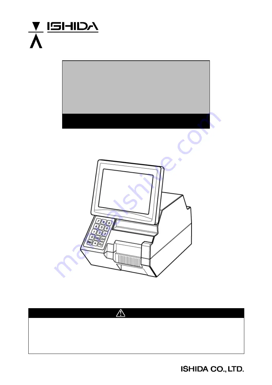
background image


IL-2000SA 


SERVICE MANUAL 


First Edition, November 2007 


Manual No. RS-61021-11 


CAUTION


READ AND UNDERSTAND THIS MANUAL 

  Thoroughly read and understand this manual before installing, operating, inspecting, or 

servicing the machine. 

  Keep this manual in a safe place where you can refer to it whenever necessary. 


DISCONTINUED

107743

Summary of Contents for IL-2000SA

Page 1: ...S 61021 11 CAUTION READ AND UNDERSTAND THIS MANUAL Thoroughly read and understand this manual before installing operating inspecting or servicing the machine Keep this manual in a safe place where you can refer to it whenever necessary D I S C O N T I N U E D 107743 ...

Page 2: ...This manual shall not be copied without permission This manual is protected by copyright and is intended solely for use in conjunction with the machine Please notify us before copying or reproducing this manual in any manner for any other purpose D I S C O N T I N U E D ...

Page 3: ...h handling the machine have increased due to new materials new processing methods and higher processing speeds and it is impossible to predict all of the possible dangers Likewise there are far too many operations which cannot or should not be performed to fully describe all of them in the manual Please assume that any operation not specifically described in this manual should never be performed S...

Page 4: ...ed the information provided in this manual Failure to heed precautions can result in personal injury or property damage The following signal words are used in this manual Indicates a potentially hazardous situation which if not avoided will result in minor or moderate injury or may result in serious injury or death Additionally there may be significant property damage Indicates a potentially hazar...

Page 5: ...ing Description 2 4 Chapter 3 TEST MODE 3 1 3 1 START UP OF TEST MODE 3 1 3 2 TEST MODE HIERARCHICAL CHART 3 2 3 3 KEY CHECK 3 3 1 Numeric Key Check 3 3 2 Touch Panel Adjustment 3 4 3 4 ALL DIAGNOSIS 3 5 3 5 MEMORY CLEAR 3 6 3 6 DISPLAY CHECK 3 7 3 7 PRINTER ADJUSTMENT 3 8 3 8 ROM VERSION 3 12 3 9 COMMUNICATION CHECK 3 13 3 10 OPTION CHECK 3 15 3 11 MEMORY DATA 3 16 3 12 DATE SET 3 17 Chapter 4 SY...

Page 6: ...5 3 3 Password Setting 5 3 4 Preset 5 4 5 Reference Data Setting 5 5 6 Total Setting 5 6 7 Report Setting 5 6 8 Cassette Link Setting 5 7 9 Date Display Setting 5 8 10 Key Image Select 5 8 5 3 SET UP MENU 2 5 9 1 System Data Setting 5 10 2 Barcode Setting 5 11 3 Item Code Setting 5 11 4 PLU Update 5 12 5 Serial Number Setting 5 12 6 Book Setting 5 13 7 Memory Card Setting 5 13 8 Master Initial Val...

Page 7: ...CD with back light 640 480 dots Preset keys 3960 40 x 99 pages Memory capacity Standard 34 MB Communications TCP IP 10 100 Base T Ethernet Interface Two PCMCIA slots Printing method Direct thermal method Thermal print head 3 inches 76 mm Printing speed 4 100 mm per second Label size Label width 1 5 3 1 30 mm to 80 mm Label length 1 2 7 9 30 mm to 200 mm Label roll Inside diameter 1 6 40 mm Outside...

Page 8: ... 480 dots 2 7 7 inch touch panel is adopted for operation panel 3 3 inch thermal head is adopted IL 2000SA 3 inches 4 Printing speed becomes faster IL 2000SA 100 mm second 5 3 inch wide label can be printed IL 2000SA 3 inch The print effective width is as follows IL 2000SA 76 mm 6 The mechanism is simplified by adopting the prism for the label sensor transparent type and the machine height can be ...

Page 9: ...terlock is installed IL 2000SA RS 232C port 10 The card slot PCMCIA port is provided IL 2000SA PCMCIA port 11 CompactFlash flash ROM is adopted for the program storage IL 2000SA CompactFlash CompactFlash 32 Mbyte OS Application program Flash ROM 1 Mbyte Boot program D I S C O N T I N U E D ...

Page 10: ...D I S C O N T I N U E D ...

Page 11: ...Chapter 2 INSTALLATION IL 2000SA Service Manual 2 1 CHAPTER INSTALLATION 2 1 OUTER DIMENSIONS 2 Power supply cable 1 8m D I S C O N T I N U E D ...

Page 12: ...TENTS OF THE PACKAGE Check that the following items are included in a package 1 IL 2000SA 2 User s manual 3 Head cleaning sheet sheet wrapping film 68 5054 09 4 Cleaning pen 1 Items Required at the Delivery 1 C F card 2 C F card adapter D I S C O N T I N U E D ...

Page 13: ...rature range 0 to 40 C humidity 20 to 85 no condensation 2 Power supply voltage must be stable 2 Connecting Options Connecting wand scanner Remove the cover at the lower part of the back of the display unit Connect the scanner to the round shape DIN socket 3 Power Supply Specification of the power supply is provided on the specification plate Make sure to use an appropriate power supply Power supp...

Page 14: ...nce 4 Activate the system menu 5 Set sale mode 6 Set a machine number 7 Set the holding data 8 Set the automatic update 9 Set the cassette 10 Set the label 11 Set the format 12 Set the printing item 13 Check the barcode 14 Check the file 15 Input output the file 16 Activate the setting menu 17 Refer to the User s Manual to set necessary items 18 Activate the registration menu 19 Refer to the User ...

Page 15: ... to start Test Mode Enter 4 9 5 3 4 4 and touch TEST MODE to start the Test Menu z How to advance each item Press the touch key of the item to be selected on the screen z How to return to the previous menu Touch the MENU key to return the display to the previous menu screen 3 D I S C O N T I N U E D ...

Page 16: ...T MODE 3 2 IL 2000SA Service Manual 3 2 TEST MODE HIERARCHICAL CHART The modes All diagnostic and Time Date setting described in the dotted line are only for the product check in the factory D I S C O N T I N U E D ...

Page 17: ...3 KEY CHECK 1 Numeric Key Check z Operation Press each numeric key then the corresponding screen key displays in reverse The left screen is an example when 8 key is pressed After a while the reversed key on the screen is cleared D I S C O N T I N U E D ...

Page 18: ...quid crystal screen and the touch panel in the main body memory If this is poorly adjusted the screen key position is misaligned Coordinates of the inputted touch panel are displayed at the bottom left corner of the screen If the screen key position misalignment occurs perform the following key operation on the operating console while in the Main Menu to enter this mode D I S C O N T I N U E D ...

Page 19: ...ead dot status check Thermal head failure check 1 Defect of thermal head 2 Defect of P 909 3 Defect of harness C2 thermal head 63 5585 04 RS 232C D sub loop check RS 232C hardware check The check cable is required 1 Defect of P 910 2 Defect of P 907 3 Defect of harness C2 RS 232C 63 8459 20 Card slot upper check PCMCIA upper hardware check The check cable is required 1 Defect of P 910 Card slot lo...

Page 20: ...t When the processing ends normally OK is displayed If an error occurs the defect of P 910 is assumed SRAM Clear All masters are cleared except the system master System Data Initialization The system master is returned to the initial values and the system data is set to the initial values Test Data Setting The master for test is set D I S C O N T I N U E D ...

Page 21: ...NS BR or CSTM ns key is touched each test is carried out Horizontal Vertical Perform a visual check to confirm whether there is any missing dot on the operator display Rear Display Perform a visual check to confirm whether there is any missing dot on the customer display D I S C O N T I N U E D ...

Page 22: ...e There are two setting methods Method 1 When the SET key of the Head Resistance is touched values set to the thermal head will be read and stored in the in the memory of the main body Method 2 Read the resistance described on the thermal head and touch the SET key after entering the value using the numeric keys Enter the thermal head resistance SET D I S C O N T I N U E D ...

Page 23: ...of the peel sensor level Head Status Check The head failure check is executed The following causes are assumed when an error is displayed 1 Defect of the thermal head 2 Defect of the P 909 board 3 Defect of the harness C2 thermal head Cassette No Head up c c c c z Cassette Status The contents detected by the cassette sensor are displayed The z seals are affixed to the cassette to shield the light ...

Page 24: ...reen when the LABEL SENSOR LEVEL button is touched 4 Touch keys to make the numeric value around 120 This value is assumed as Numeric value A 5 Touch the FEED key several times again to issue one label At this time the label sensor is detecting the label and the backing paper This value is assumed as Numeric value B 6 When the result of Numeric value A Numeric value B is 60 or more the adjustment ...

Page 25: ...s to make the numeric value around 100 4 Touch the FEED key to issue one label At this time confirm that the peel sensor is shielded by the label 5 Confirm that the numeric value of PEEL SENSOR LEVEL is 20 or less Note If the value is more than 20 adjust the optical axis by bending the steel plate of the emitting sensor bracket Printer Adjustment Touch the PAGE key and set each item to perform tes...

Page 26: ...Chapter 3 TEST MODE 3 12 IL 2000SA Service Manual 3 8 ROM VERSION z Operation Each software program can be confirmed on this screen Screen Example D I S C O N T I N U E D ...

Page 27: ...IL 2000SA Service Manual 3 13 3 9 COMMUNICATION CHECK z Operation Touch the EXECUTE key of the corresponding check part Connect the cable with each cable test referring to each connection method 1 4 D I S C O N T I N U E D ...

Page 28: ...Defect of P 907 2 Defect of P 910 3 Defect of harness C3 communication 63 8468 23 ILAN loopback test Driver Æ receiver communication test 1 Defect of P 910 ILAN RAM test Communication buffer read write test 1 Defect of P 910 ILAN cable test Main body Æ IF 21FD communication test Refer to connection method 2 1 Defect of P 907 2 Defect of P 910 3 Defect of harness C3 communication 63 8468 23 RS 232C...

Page 29: ... option Scanner Read Data The result of reading the barcode is displayed Slot 1 Check Insert the CF card into the slot 1 and touch the EXECUTE key Slot 2 Check Insert the CF card into the slot 2 and touch the EXECUTE key Drawer Open Check Connect the drawer and touch the EXECUTE key to open the drawer D I S C O N T I N U E D ...

Page 30: ...TEST MODE 3 16 IL 2000SA Service Manual 3 11 MEMORY DATA Do not change the data If the data is changed the machine does not operate normally z Operation SRAM and FROM data can be confirmed D I S C O N T I N U E D ...

Page 31: ...0SA Service Manual 3 17 3 12 DATE SET z Operation Same as the date time setting of the setup mode This mode is used for machine operation test at factory Date setting can also be performed in the Set Mode D I S C O N T I N U E D ...

Page 32: ...D I S C O N T I N U E D ...

Page 33: ...stem Setting Menu While in the Main Menu enter 4 9 5 3 4 4 and press the PLU key on the operating console to enter the System Setting Menu z How to advance each item Press the touch key of the item you want to select z How to return to the previous menu Touch the MENU key to return the display to the previous menu 4 D I S C O N T I N U E D ...

Page 34: ...Chapter 4 SYSTEM SETTING MENU 4 2 IL 2000SA Service Manual 4 2 HIERARCHICAL CHART OF SYSTEM SETTING MENU D I S C O N T I N U E D ...

Page 35: ...Chapter 4 SYSTEM SETTING MENU IL 2000SA Service Manual 4 3 4 3 SALE MODE SETTING z Operation Touch to select one of the keys to set whether the operator system is used or not D I S C O N T I N U E D ...

Page 36: ...system referring to the figure below The department number is used when managing the master for each department with the personal computer connected Store in line specification z Selection Touch one of the keys to select the desired function z Setting Enter the numeric value and touch the SET key D I S C O N T I N U E D ...

Page 37: ... change is made the changed date and time are printed The date and time return the clock date and time when the next commodity is called DATE The clock date and time are printed at the time when a label is issued Reg hold No The register code is not held Yes The register code is held PLU hold No The PLU name is not held after the print ends in the manual mode Yes The PLU name is held for the calle...

Page 38: ...ibition of quick fixed print No Fixed price label issue is not prohibited at zero point Yes Fixed price label issue is prohibited at zero point Total back time Timeout period setting for changing from the subtotal screen to the normal screen D I S C O N T I N U E D ...

Page 39: ...page touch the PAGE key z Selection Touch one of the keys to select the desired function No The data which is temporarily changed in the operation mode is not reflected in the PLU master Yes The PLU master is updated automatically with the data temporarily changed in the operation mode When the RAM is cleared everything is set to No D I S C O N T I N U E D ...

Page 40: ...CSV format NONE Do not save CF 2 Insert the CF card into the bottom slot to save SRAM 1 Insert the S RAM into the upper slot to save SRAM 2 Insert the S RAM into the bottom slot to save HOST LINKAGE NONE No linkage Ethernet CARD Linking to PC via Ethernet Achieved Delete Msg REGULAR Displayed at normal mode start When there is record other than today s a message is displayed MEMO SHORTAGE Displaye...

Page 41: ...ansaction data DIF TRANSACTION Differential transaction data SUMMARY Summary data ResponseFile Response telegraphic message NONE Do not add any control code WITH ControlCD Add control code ID Control Renewal Select Select a header unit of a CSV file NO ID CONTROL RENEW Do not use a control code ID Add 0 to 2 to control the update of each data 0 Rewrite 1 Prioritize the internal master and do not r...

Page 42: ...cations Preset Page Set a page number of the default preset key Individual With backing paper Set whether the label is peeled off or issued with the backing paper Manual Auto Set whether the label is issued manually or automatically as a default data Continuous Set whether the die cut or continuous label is used Shop Address Set whether the shop name and address are printed on the label or not Fie...

Page 43: ...Chapter 4 SYSTEM SETTING MENU IL 2000SA Service Manual 4 11 Over length flag Set whether or not to print the text that exceeds the specified length D I S C O N T I N U E D ...

Page 44: ...Initial value 2 0 mm Preprint Feed Set the amount in the unit of 0 1mm for the preprint feed Initial value 7 5 mm Print direction Normal direction Reverse direction Back Feed Used with No IL 2000SA cannot be used with the back feeding Yes It is prepared in consideration of a future model development Label Sensor Used with Label Sensor Ä Set as No use when the receipt is used and too thin to detect...

Page 45: ...e density is optimum at 5 If the density is too thin adjust the thermal head position Two color print density 0 9 Optional Two color print is incapable with this machine Item No Set an item number for test printing Format Information The set information is displayed D I S C O N T I N U E D ...

Page 46: ...0SA Service Manual 4 10 FORMAT SETTING There are two pages for format setting To change the page touch the PAGE key This mode is used to create the label format Ä Refer to Appendix Label Formatting for more information D I S C O N T I N U E D ...

Page 47: ...TTING 5X7 Print Select Select the 5X7 print content Register Code Select Decide whether to print either one of the register or the shop code Markdown Price Print Select Select one of the three types Comment Print Position Select Select column of the comment POP Print Position Select Select column of POP name Register Code Print Position Select Select the register code print position Print position...

Page 48: ...ster s by touching the one of SELECT and SELECT ALL key and initialize by touching the EXECUTE key Even if initialization is performed for all masters by touching SELECT ALL and EXECUTE keys a part of basic master is written Therefore the PLU master conversion number of files does not become 0 because memory is partially used D I S C O N T I N U E D ...

Page 49: ...thod Connect the machine with the DataRapid referring to the figure below z Select the processing xWhen writing the machine data in the DataRapid Select Main xWhen writing the DataRapid data in the machine Select Main xWhen deleting the files in the DataRapid Select DELETE D I S C O N T I N U E D ...

Page 50: ...tion Touch the BARCODE key on the SYSTEM MENU screen z Selection Enter the desired starting number and ending number z Print Touch the PRINT key to print a barcode check label Touch the CANCEL key to stop printing z Continue Touch the CONTINUE key to keep printing D I S C O N T I N U E D ...

Page 51: ...Set Up Menu The Set Up Menu screen appears z How to select the desired item Press the touch key of the item you want to select on the screen z How to display Set Up Menu 2 screen To display Set Up menu 2 screen enter 9 9 9 and touch the PAGE key z How to return the display to Main Menu To return the display to the Main Menu touch the MENU key on the screen 5 D I S C O N T I N U E D ...

Page 52: ...time key on the Set Menu screen z How to set the date and time Enter the desired date or time For example enter 10102007 to set the date as October 10 2007 Then touch the DATE key to update the date z How to return the display to Main Menu To return the display to the Main Menu touch the MENU key on the screen D I S C O N T I N U E D ...

Page 53: ...xt Touch to select the desired field and touch the EDIT key to access the edit screen z How to return the display to Main Menu To return the display to the Main Menu touch the MENU key on the screen 3 Password Setting z How to display this screen Touch the PASSWORD SET key on the Set Up Menu screen z How to set the password Enter the desired password 6 digits to be applied for the selected mode s ...

Page 54: ...t Up Menu screen z How to select the desired field Touch to select the desired field for each reference data z How to display the next page To display the next page touch the PAGE key z How to return the display to Main Menu To return the display to the Main Menu touch the MENU key on the screen D I S C O N T I N U E D ...

Page 55: ... to select the desired field for each reference data z How to set the desired numeric value Enter the desired numeric value for each reference data and touch the corresponding SET key z How to display the next page To display the next page touch the PAGE key z How to return the display to Main Menu To return the display to the Main Menu touch the MENU key on the screen D I S C O N T I N U E D ...

Page 56: ...To display the next page touch the PAGE key z How to return the display to Main Menu To return the display to the Main Menu touch the MENU key on the screen 7 Report Setting z How to display this screen Touch the REPORT key on the Set Menu screen z How to select Day Total or Total Touch either Day Total or Total to select the desired report type z How to select individual report or all reports Tou...

Page 57: ...y on the Set Up Menu screen z How to select the desired field Touch to select the desired field for each reference data z How to display the next page To display the next page touch the PAGE key z How to return the display to Main Menu To return the display to the Main Menu touch the MENU key on the screen D I S C O N T I N U E D ...

Page 58: ... the display to Main Menu To return the display to the Main Menu touch the MENU key on the screen 10 Key Image Select This function is used to list images stored in the machine and select the desired image to be used z How to display this screen Touch the KEY IMAGE key on the Set Up Menu screen z How to select the image Touch to select the desired image area z How to paste on the preset key Touch ...

Page 59: ...Chapter 5 SET UP MENU IL 2000SA Service Manual 5 9 5 3 SET UP MENU 2 To display the Set Up menu 2 screen enter 9 9 9 and touch the PAGE key D I S C O N T I N U E D ...

Page 60: ...esired field Touch to select the desired field for each data z How to set the desired numeric value Enter the desired numeric value for each data and touch the SET key z How to display the next page To display the next page touch the PAGE key z How to return the display to Main Menu To return the display to the Main Menu touch the MENU key on the screen D I S C O N T I N U E D ...

Page 61: ...ch the corresponding field to display a selection list Then touch to select the desired item field z How to return the display to Main Menu To return the display to the Main Menu touch the MENU key on the screen 3 Item Code Setting After selecting the code type set the code digit 4 digit classification code and 8 digit JAN code z How to display this screen Touch the ITEM CODE key on the Set Up Men...

Page 62: ...ow to return the display to Main Menu To return the display to the Main Menu touch the MENU key on the screen 5 Serial Number Setting z How to display this screen Touch the PLU UPDATE key on the Set Up Menu screen z How to set the desired numeric value Enter the desired numeric value for each data and touch the corresponding field z How to select the desired item Touch the corresponding field to d...

Page 63: ... How to return the display to Main Menu To return the display to the Main Menu touch the MENU key on the screen 7 Memory Card Setting z How to display this screen Touch the PLU UPDATE key on the Set Up Menu screen z How to set the desired numeric value Enter the desired numeric value for each data and touch the corresponding field z How to select the desired item Touch the corresponding field to d...

Page 64: ...t Up Menu screen z How to select the desired item Touch one of yellow buttons to display a selection list Then touch to select the desired item field z How to set the desired numeric value For blue buttons enter the desired numeric value and touch the corresponding field z How to return the display to Main Menu To return the display to the Main Menu touch the MENU key on the screen D I S C O N T I...

Page 65: ...Chapter 6 HARDWARE CONFIGURATION IL 2000SA Service Manual 6 1 CHAPTER HARDWARE CONFIGURATION 6 1 MECHANICAL COMPONENTS 1 Main Unit 6 D I S C O N T I N U E D ...

Page 66: ...Chapter 6 HARDWARE CONFIGURATION 6 2 IL 2000SA Service Manual 2 Printer Unit D I S C O N T I N U E D ...

Page 67: ...Chapter 6 HARDWARE CONFIGURATION IL 2000SA Service Manual 6 3 3 Display Unit Touch Panel Volume Inverter LCD D I S C O N T I N U E D ...

Page 68: ...Chapter 6 HARDWARE CONFIGURATION 6 4 IL 2000SA Service Manual 6 2 ELECTRICITY 1 Electric Block D I S C O N T I N U E D ...

Page 69: ...Chapter 6 HARDWARE CONFIGURATION IL 2000SA Service Manual 6 5 2 Board Setting 1 Main board P 910 When replacing the board make sure to turn ON the battery switch D I S C O N T I N U E D ...

Page 70: ...ection Other side 1 TXD Æ 2 RS 232C P 919 2 RTS Æ 4 3 RXD Å 1 4 CTS Å 3 5 DC 5 V 8 6 SG 5 7 XJ6 No Signal name Direction Other side 1 DC 24 V Å P 909 XJ9 2 GND XJ7 No Signal name Direction Other side 1 to 24 KEYBORD control signal Keyboard P 944 XJ1 25 to 27 Vcc DC 5 V Æ 28 to 30 GND XJ9 No Signal name Direction Other side 1 to 8 Data LDO to LD7 Liquid crystal display Through P 919 9 Vcc DC 5 V Æ ...

Page 71: ...r side A0 to A60 B0 to B60 Signal between P 909 and P 910 P 910 XJ3 XJ3 No Signal name Direction Other side 1 B phase Æ Stepping motor 2 B phase Æ 3 A phase Æ 4 A phase Æ 5 B COM 6 A COM XJ6 No Signal name Direction Other side 1 3 5 7 9 GND Thermal head 2 4 6 8 10 VH DC 24 V Æ 11 GND 12 13 VCC DC 5 V Æ 14 to 34 Signal between thermal heads P 909 D I S C O N T I N U E D ...

Page 72: ...ssette 1 5 Cassette 2 Vcc Æ 6 Cassette 2 7 Head up Vcc Æ 8 Head up 9 GND XJ12 No Signal name Direction Other side 1 Vcc Receiver Æ Label sensor 2 GND Emitter Æ 3 Vcc Receiver Å 4 Sensor signal Receiver Å 5 XJ13 No Signal name Direction Other side 1 Vcc Emitter Æ Peel sensor 2 GND Emitter 3 Vcc Receiver Æ 4 Sensor signal Receiver Å 3 Power Supply Unit z I O signals CN1 No Signal name Direction Othe...

Page 73: ...al name Direction Other side 1 12 V Æ Inverter 2 GND XJ9 No Signal name Direction Other side 1 to 4 Touch panel signal Touch panel XJ12 No Signal name Direction Other side 1 to 4 6 8 to 15 Liquid crystal display signal Æ LCD indicator 5 7 GND XJ13 No Signal name Direction Other side 1 3 16 18 DC 12 V Å P 919 1 XJ2 Liquid crystal display signal Å 2 8 10 17 19 25 GND XJ14 No Signal name Direction Ot...

Page 74: ...XJ7 No Signal name Direction Other side 1 2 GND Option display 3 24V Æ XJ11 No Signal name Direction Other side 1 to 9 I 2 NET ILAN XJ12 No Signal name Direction Other side 1 to 9 I 2 NET ILAN XJ13 No Signal name Direction Other side 1 to 9 I 2 NET ELAN XJ14 No Signal name Direction Other side 1 to 9 I 2 NET ELAN XJ15 No Signal name Direction Other side 1 to 9 RS 232C RS 232C XJ15 XJ14 XJ12 XJ11 X...

Page 75: ...de Display signal Æ P 917 XJ13 GND XJ3 No Signal name Direction Other side Display signal Å P 910 9 Vcc Å 10 GND 12 13 34V Å XJ4 No Signal name Direction Other side 1 TxD Å P 910 XJ5 RS 232C 2 RTS Å 3 RxD Æ 4 CTS Æ 5 DC 5V 6 SG 7 FG XJ6 No Signal name Direction Other side 1 DC 12 V P 910 2 GND 3 ON OFF XJ7 No Signal name Direction Other side 1 DC 12 V P 910 2 GND XJ2 XJ1 XJ3 XJ6 XJ7 XJ4 XJ2 XJ5 D ...

Page 76: ...D I S C O N T I N U E D ...

Page 77: ...1 Printer cover is located at the right side of the front 2 Pull out the cassette 3 Lift the cover 4 Slide the right side of the cover to the rear The cover will be damaged if the cover contacts the printer bracket 5 Slide the left side to the rear to remove the cover Cover 7 D I S C O N T I N U E D ...

Page 78: ...Resistance value setting and running distance resetting are required to exchange the thermal head Refer to page 3 7 1 Lift the thermal head with the bracket and pull it with both hands 2 Remove the connector 3 Remove the thermal head out of the bracket and mount a new thermal head 4 Mount the connector 5 Hold the thermal head with both hands to mount it on the printer D I S C O N T I N U E D ...

Page 79: ...bracket comes to the same end of the thermal head stay Then lightly tighten the screws Try to perform test printing to decide the appropriate position b If printing is too light over the label The cause can be assumed that the center line of the heating element of the thermal head and the center line of the print roller are misaligned to the front or back in parallel Therefore move the fixing scre...

Page 80: ...l 1 Fixing screw 4 Head bracket 3 Thermal head stay Front end of bracket Front end of stay Adjustment by moving the stay Uneven printing Misaligned printing left right 2 Printer bracket Figure 1 Positioning of the thermal head D I S C O N T I N U E D ...

Page 81: ... the printer cover in advance See 7 1 DETACH OF PRINTER COVER 1 Remove the screws for the thermal head Be careful not to lose the collars 2 Remove the bracket 3 Remove the label sensor 4 Replace the bell sensor 5 Check the sensor mounting side 6 Mount the bracket D I S C O N T I N U E D ...

Page 82: ...e are two peel sensors One is at the receiver side and another at the emitter side 2 Loosen the fixed screws to remove the sensor 3 Remove the connector to remove the sensor 4 Adjust the protrusion portions to the holes to mount 5 Do the same as 4 for other side D I S C O N T I N U E D ...

Page 83: ...NTENANCE IL 2000SA Service Manual 7 7 7 6 EXCHANGE OF CASSETTE SENSOR 1 Pull out the cassette 2 The sensor is fixed by two screws 3 Remove the screws 4 Remove the connector out of the sensor D I S C O N T I N U E D ...

Page 84: ...e four screws that fix the display unit If a screwdriver cannot reach those screws change the angle of the display unit Display unit Remove these screws 7 8 DETACH OF TOP COVE The top cover needs to be removed to remove the display unit Refer to 7 7 The top cover is fixed by seven screws 2 screws 2 screws 2 screws inside the cover 1 screw D I S C O N T I N U E D ...

Page 85: ...of XJ7 of P 910B 2 or contact failure x Defect of the numeric keypad Displacement of the touch panel keys Displacement of the display key buttons and touch input x Adjust the touch panel of the test mode x If the positioning cannot be recovered replace the display unit Display is dark x Defect of the volume x Defect of the back light x Defect of the back light inverter board The printer does not w...

Reviews: