IFM Electronic ecomot200 DL0203, Operating Instructions Manual
The IFM Electronic ecomot200 DL0203 comes with an easily accessible, user-friendly Operating Instructions Manual that can be downloaded for free from manualshive.com. This comprehensive manual provides detailed guidance and essential information on operating the product efficiently and effectively.
Share
Download


Reviews:
No comments
Related manuals for ecomot200 DL0203

PR102 MINI-PLC 40 I/O
Brand: Akytec Pages: 2

DIN4
Brand: DLI Pages: 57

001DC009AC
Brand: CAME Pages: 12

ecomat 200 Monitor AL-3
Brand: IFM Electronic Pages: 64

SBC23A
Brand: GE Pages: 60

SBC231A
Brand: GE Pages: 28

IFC51AD
Brand: GE Pages: 8
REL650 series
Brand: ABB Pages: 516

HSR-SL Series
Brand: HANYOUNGNUX Pages: 2

SEL-321-2
Brand: Schweitzer Engineering Laboratories Pages: 354

RM347C Series
Brand: Stelpro Pages: 2

SSRSMC3/32 Series
Brand: elco Pages: 4
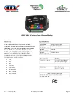
CERV-IR-4
Brand: Build Equinox Pages: 2

rialto
Brand: Astrel Group Pages: 40


