


SBOX-100-QM87i Fanless Marine Computer
Page I
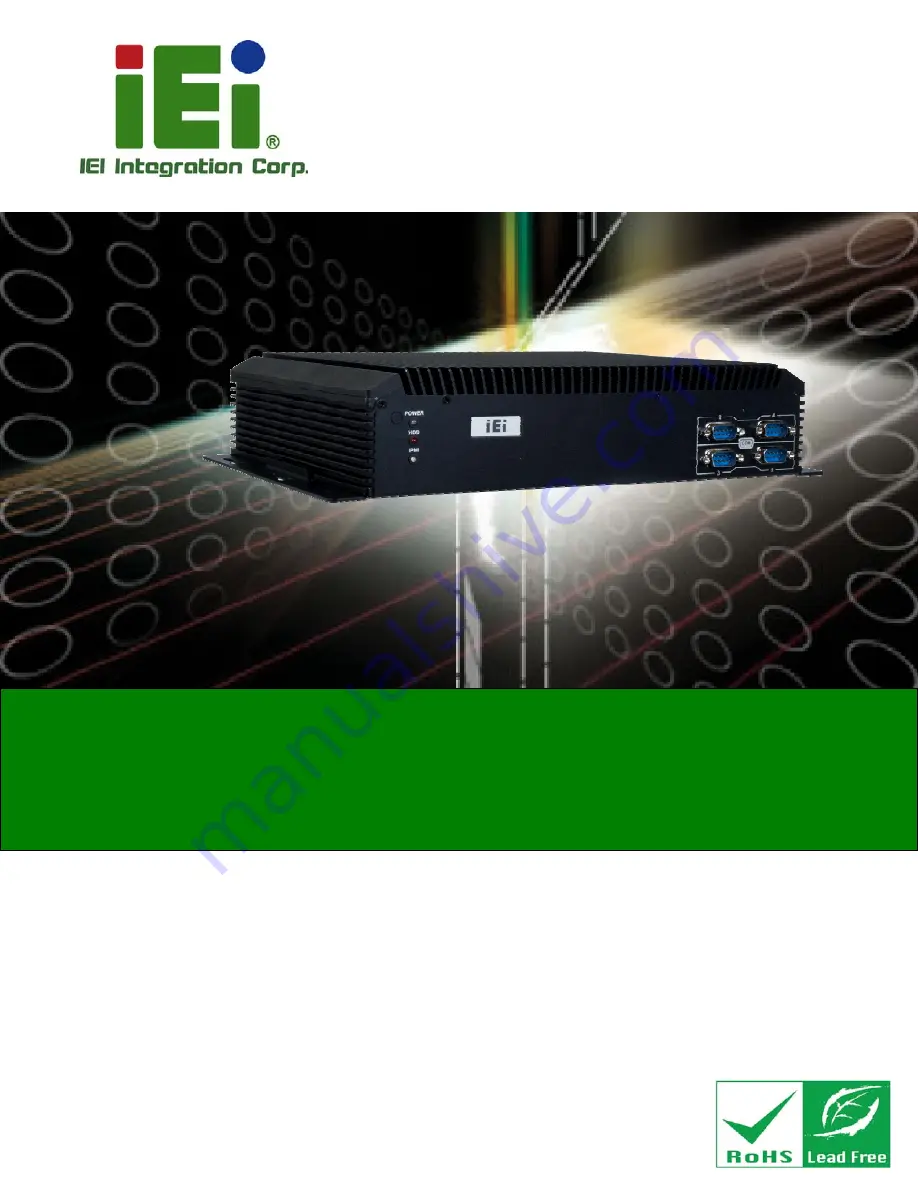
User Manual
Fanless Marine Computer with Intel® Core™ i5-4400E
Dual-Core CPU, Intel® QM87 Express Chipset, GbE LAN,
HDMI, DVI-D, VGA, CAN Bus, CFast Slot, RS-232/422/485,
USB 2.0, USB 3.0, iRIS-2400, RoHS Compliant
MODEL:
SBOX-100-QM87i
Rev. 1.00 – June 4, 2015
Summary of Contents for SBOX-100-QM87i
Page 12: ......
Page 13: ...SBOX 100 QM87i Fanless Marine Computer Page 1 Chapter 1 1 Introduction ...
Page 20: ...SBOX 100 QM87i Fanless Marine Computer Page 8 Chapter 2 2 Unpacking ...
Page 24: ...SBOX 100 QM87i Fanless Marine Computer Page 12 Chapter 3 3 Installation ...
Page 38: ...SBOX 100 QM87i Fanless Marine Computer Page 26 Chapter 4 4 BIOS Setup ...
Page 76: ...SBOX 100 QM87i Fanless Marine Computer Page 64 Chapter 5 5 Maintenance ...
Page 80: ...SBOX 100 QM87i Fanless Marine Computer Page 68 Chapter 6 6 Interface Connectors ...
Page 96: ...SBOX 100 QM87i Fanless Marine Computer Page 84 Appendix A A Regulatory Compliance ...
Page 101: ...SBOX 100 QM87i Fanless Marine Computer Page 89 Appendix B B Safety Precautions ...
Page 106: ...SBOX 100 QM87i Fanless Marine Computer Page 94 Appendix C C BIOS Menu Options ...
Page 109: ...SBOX 100 QM87i Fanless Marine Computer Page 97 Appendix D D Watchdog Timer ...
Page 112: ...SBOX 100 QM87i Fanless Marine Computer Page 100 E Hazardous Materials Disclosure Appendix E ...


