


AVL-3000 Advanced Auto Data Server
Page i
IEI Technology Corp.
User Manual
MODEL:
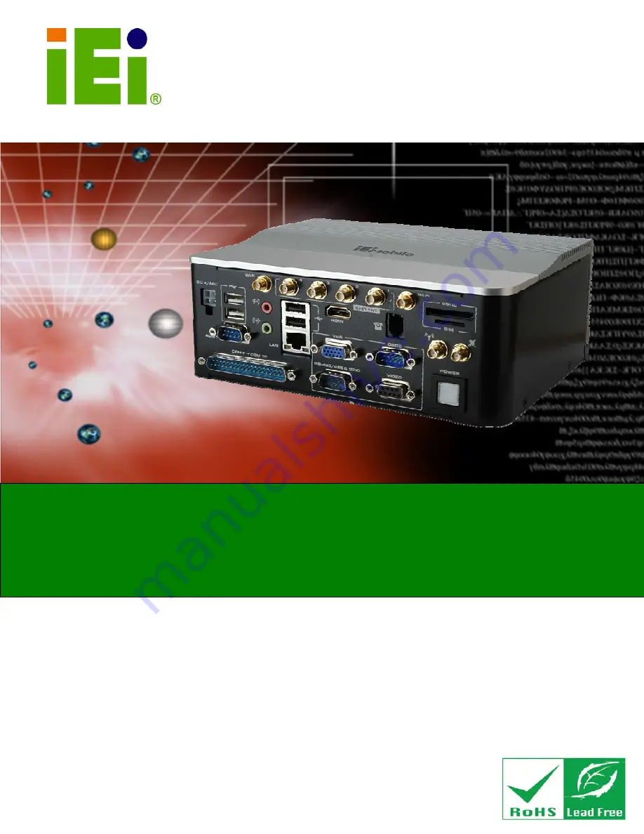
AVL-3000
Advanced Auto Data Server with Intel® Atom™ N2600 1.6 GHz
CPU, On-board 2.0 GB DDR3 Memory, 802.11b/g/n Wireless,
HSUPA, GPS with DR, OBD-II, USB, Audio,
4-Channel Software Video Capture, RoHS Compliant
Rev. 1.00 – 10 September, 2012
Summary of Contents for AVL-3000
Page 14: ...AVL 3000 Advanced Auto Data Server Page 1 Chapter 1 1 Introduction ...
Page 22: ...AVL 3000 Advanced Auto Data Server Page 9 Chapter 2 2 Unpacking ...
Page 26: ...AVL 3000 Advanced Auto Data Server Page 13 Chapter 3 3 Installation ...
Page 44: ...AVL 3000 Advanced Auto Data Server Page 31 Chapter 4 4 BIOS ...
Page 73: ...AVL 3000 Advanced Auto Data Server Page 60 Appendix A A OBD II Reader Command ...
Page 82: ...AVL 3000 Advanced Auto Data Server Page 69 Appendix B B One Key Recovery ...
Page 90: ...AVL 3000 Advanced Auto Data Server Page 77 Figure B 5 Partition Creation Commands ...
Page 124: ...AVL 3000 Advanced Auto Data Server Page 111 Appendix C C Watchdog Timer ...
Page 127: ...AVL 3000 Advanced Auto Data Server Page 114 Appendix D D Hazardous Materials Disclosure ...


