manualshive.com logo in svg
background image


AFL2-17A/AB-H61 


Page I 

Us e r  Ma n u a l 

AFL2-17A/AB-H61 S e rie s  

MODEL: 

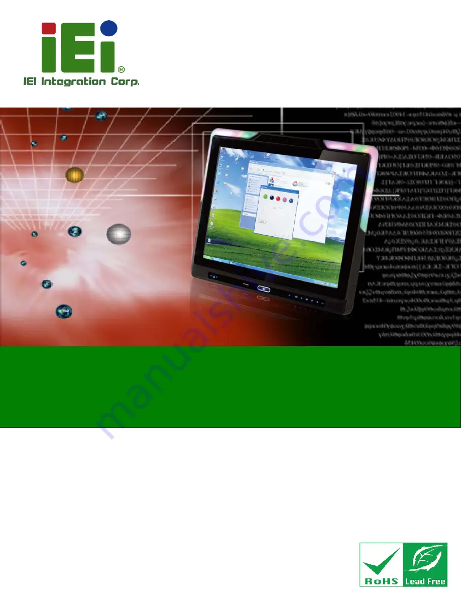
Flat Bezel Panel PC with 2nd Generation Intel® Core™ i7/ i5/ i3, 

Pentium® and Celeron® processor, Touch Screen, Wi-Fi, USB, 

Dual GbE LAN , RS-232/422/485, 1.3M pixels Camera,   

HD Audio and RoHS 


Re v. 1.23 - 25 Ap ril, 2014 

Us e r  Ma n u a l 

Содержание AFL2-17A-H61 Series

Страница 1: ...2 17A AB H61 Series MODEL Flat Bezel Panel PC with 2nd Generation Intel Core i7 i5 i3 Pentium and Celeron processor Touch Screen Wi Fi USB Dual GbE LAN RS 232 422 485 1 3M pixels Camera HD Audio and R...

Страница 2: ...CPU temperature alert LED in Section 1 2 1 1 LED Indicators 14 May 2013 1 21 Update the mechanical keys to film keys 18 April 2013 1 20 Add Section 1 2 1 2 LED light 4 January 2013 1 11 Remove Section...

Страница 3: ...ising out of the use or inability to use the product or documentation even if advised of the possibility of such damages This document contains proprietary information protected by copyright All right...

Страница 4: ...m Panel 9 1 2 4 Left Side Panel 10 1 2 5 Right Side Panel 11 1 3 INTERNAL OVERVIEW 11 1 4 SYSTEM SPECIFICATIONS 12 2 LED LIGHT BAR OPTIONAL 14 2 1 OVERVIEW 15 2 2 IEI LED LIGHT BAR DISPLAY SIMULATOR 1...

Страница 5: ...LED Blink 2 34 3 DETAILED SPECIFICATIONS 37 3 1 DIMENSIONS 38 3 2 INTEL CORE DESKTOP PROCESSOR 39 3 3 MOTHERBOARD COMPONENTS 39 3 3 1 Memory Capacity 39 3 3 2 Storage Capacity 39 3 4 EXTERNAL PERIPHE...

Страница 6: ...Mounting 64 5 13 3 Stand Mounting 65 5 13 4 Arm Mounting 66 5 14 EXTERNAL PERIPHERAL DEVICE CONNECTION 67 5 14 1 Audio Connection 68 5 14 2 HDMI Device Connection 69 5 14 3 LAN Connection 71 5 14 4 S...

Страница 7: ...Ie Mini Card Slot 102 6 2 22 Power Button Connector 103 6 2 23 RFID Connector 103 6 2 24 SATA 3Gb s Drive Connectors 104 6 2 25 SATA Power Connector 105 6 2 26 Speaker Connector 106 6 2 27 Touch panel...

Страница 8: ...ACPI Settings 129 8 3 2 RTC Wake Settings 130 8 3 3 Trusted Computing 131 8 3 4 CPU Configuration 132 8 3 4 1 CPU Information 133 8 3 5 SATA Configuration 135 8 3 6 Intel TXT LT Configuration 136 8 3...

Страница 9: ...IVER INSTALLATION 187 9 11 LED BAR DRIVER INSTALLATION 191 9 12 AMCAP DRIVER INSTALLATION 194 10 COOLING MANAGEMENT CONSOLE ICMC 197 10 1 OVERVIEW 198 10 1 1 iCMC Installation 198 10 2 ICMC OVERVIEW 2...

Страница 10: ...2 Backup System 241 C 5 3 Restore Your Last Backup 242 C 5 4 Manual 243 C 6 RESTORE SYSTEMS FROM A LINUX SERVER THROUGH LAN 244 C 6 1 Configure DHCP Server Settings 245 C 6 2 Configure TFTP Settings 2...

Страница 11: ...16 Figure 2 3 Confirm Installation Screen 17 Figure 2 4 Installation Complete 17 Figure 2 5 iEi LED Light Bar Display Simulator 18 Figure 2 6 Color Setting Area 19 Figure 2 7 Color Palette 20 Figure 2...

Страница 12: ...eset Button Location 59 Figure 5 16 Wall mounting Bracket 61 Figure 5 17 Chassis Support Screws 63 Figure 5 18 Secure the Panel PC 63 Figure 5 19 Cutout Dimensions 64 Figure 5 20 Tighten the Panel Mou...

Страница 13: ...re 6 22 LOGO LED Connector Location 100 Figure 6 23 Mini USB Connector Location MINUSB2 101 Figure 6 24 Mini USB Connector Location MINUSB1 101 Figure 6 25 PCIe Mini Card Slot Location 102 Figure 6 26...

Страница 14: ...rations 171 Figure 9 14 Graphics Driver Installation Finish Screen 171 Figure 9 15 Touch Screen Driver Welcome Screen 172 Figure 9 16 Touch Screen Driver License Agreement 173 Figure 9 17 Touch Screen...

Страница 15: ...InstallShield Wizard Starts 192 Figure 9 48 Welcome Screen 192 Figure 9 49 Ready to Install 193 Figure 9 50 Installation 193 Figure 9 51 Installation Complete 194 Figure 9 52 AMCap Driver Welcome Scre...

Страница 16: ...rmation 230 Figure C 19 Image Creation Complete 230 Figure C 20 Image Creation Complete 230 Figure C 21 Press Any Key to Continue 231 Figure C 22 Auto Recovery Utility 232 Figure C 23 Launching the Re...

Страница 17: ...AFL2 17A AB H61 Page XVII Figure C 39 Restore System Backup Complete Window 243 Figure C 40 Symantec Ghost Window 243...

Страница 18: ...Table 5 9 VGA Pinouts 77 Table 6 1 Peripheral Interface Connectors 82 Table 6 2 Auto dimming Connector Pinouts 83 Table 6 3 Battery Connector Pinouts 84 Table 6 4 BIOS Programming Connector Pinouts 84...

Страница 19: ...TA 3Gb s Drive Connector Pinouts 105 Table 6 25 SATA Power Connector Pinouts 106 Table 6 26 Speaker Connector Pinouts 107 Table 6 27 Touch Panel Connector Pinouts 108 Table 6 28 Touch Panel Connector...

Страница 20: ...OS Menu 10 USB Configuration 137 BIOS Menu 11 Super IO Configuration 139 BIOS Menu 12 Serial Port n Configuration Menu 139 BIOS Menu 13 Hardware Health Configuration 143 BIOS Menu 14 Serial Port Conso...

Страница 21: ...AFL2 17A AB H61 Page 1 1 Introduction Chapter 1...

Страница 22: ...ntegration into kiosk and point of sales POS applications An Intel H61 chipset ensures optimal memory graphics and peripheral I O support The system comes with 4GB DDR3 1333MHz SO DIMMs 2GB x 2 ensuri...

Страница 23: ...ies AFL2 17A H61 P R R12 Resistive Touch Yes AFL2 17AB H61 P R R12 Resistive Touch No AFL2 17A H61 P PC R12 Projected capacitive Yes AFL2 17AB H61 P PC R12 Projected capacitive No Table 1 1 AFL2 17A A...

Страница 24: ...environment control The relative errors between the detect environment temperature and the actual environment temperature are no more than 5 degrees When the environment temperature is lower than def...

Страница 25: ...a flat bezel panel TFT LCD screen surrounded by a PC ABS plastic frame The LED light bars are for AFL2 17AB H61 series only Figure 1 2 AFL2 17A AB H61 Front View 1 2 1 1 LED Indicators There are sixt...

Страница 26: ...Table 1 3 Bluetooth The Bluetooth module is enabled or disabled Controlled by the BIOS See Section 8 5 2 Auto Dimming The auto dimming function is enabled or disabled Controlled by the BIOS See Secti...

Страница 27: ...ED Light To configure the LED Indicators light through a quick and easy way please follow the steps below Step 1 Double click the LED Light exe icon to open the LED Light software Figure 1 4 LED Light...

Страница 28: ...n Key Des cription Fn LCD On Off RFID Enable Disable Fn Audio Volume Down Audio Mute Fn Audio Volume Up Camera Enable Disable Fn Brightness Down Mini USB Micro SD Enable Disable Fn Brightness Up Power...

Страница 29: ...H61 Rear View 1 2 3 Bottom Panel The bottom panel of the AFL2 17A AB H61 has the following features Figure 1 8 1 x AT ATX Switch 1 x Clear CMOS switch 1 x 9V 36V DC power jack 6 x Function keys 1 x H...

Страница 30: ...USB 3 0 connectors 1 x VGA port Figure 1 8 AFL2 17A AB H61 Bottom Panel 1 2 4 Left Side Panel The left side panel of the AFL2 17A AB H61 has the following features Figure 1 9 2 x Audio jacks Line out...

Страница 31: ...nel The right side panel of the AFL2 17A AB H61 provides access to the CD ROM optional Figure 1 10 Figure 1 10 AFL2 17A AB H61 Right Side Panel 1 3 Internal Overview The AFL2 17A AB H61 has the follow...

Страница 32: ...Core i7 i5 i3 Pentium and Celeron processor Chipset Intel H61 Ethernet Realtek RTL8111E PCIe GbE controller support ASF2 0 Memory Support two 204 pin DDR3 SO DIMM slot system max 16GB preinstalled wit...

Страница 33: ...nel Power Supply 120W power adapter Input 100V AC 240V AC 50 60 Hz Output 19V DC Power Requirement 9V 36V DC I O Ports and Switches 2 x RS 232 DB 9 connector 1 x RS 422 485 DB 9 connector 2 x GbE LAN...

Страница 34: ...AFL2 17A AB H61 Page 14 2 LED Light Bar Optional Chapter 2...

Страница 35: ...ck and easy user interface The customized functions include light scripts programmable colors light duration flash rates and light patterns 2 2 iEi LED Light Bar Dis play Simulator To configure the LE...

Страница 36: ...Step 5 The Select Installation Folder screen in Figure 2 2 appears Figure 2 2 Select Installation Folder Screen Step 6 Click Next to continue Step 7 The Confirm Installation screen in Figure 2 3 appea...

Страница 37: ...17A AB H61 Page 17 Figure 2 3 Confirm Installation Screen Step 9 The program begins to install Step 10 When the installation is complete the screen in Figure 2 4 appears Figure 2 4 Installation Compl...

Страница 38: ...it to open the iEi LED Light Bar Display Simulator as shown in Figure 2 5 Figure 2 5 iEi LED Light Bar Display Simulator The descriptions of iEi LED Light Bar Display Simulator are listed below Funct...

Страница 39: ...ons LEFT Select the left LED simulation buttons RIGHT Select the right LED simulation buttons 1 30 LED simulation buttons Table 2 1 LED Simulator Software Description Step 14 Select the color The colo...

Страница 40: ...r of selected LED simulation button will automatically change See Figure 2 8 Figure 2 8 Simulate the LED Light Step 17 If you want to set all the left LED simulation buttons for a certain color at the...

Страница 41: ...AFL2 17A AB H61 Page 21 Figure 2 9 Set the Left LEDs Step 18 If you want to set all the LED simulation buttons for a certain color at the same time click the ALL button Figure 2 10 Set All the LEDs...

Страница 42: ...note that the unit is second enter a number between 1 and 20 See Figure 2 11 Figure 2 11 Light Duration Step 20 Press the Add button to insert a new control command You may continue to set a new comma...

Страница 43: ...Page 23 Step 21 Press the Loop Start button to set loop start point Figure 2 13 Add Loop Start Step 22 Press the Loop End button to set loop end point Figure 2 14 Add Loop End Step 23 Press the Run bu...

Страница 44: ...ode 2 4 LED Control API 2 4 1 Introduction This chapter aims to explain how to use LED Light Bar Control API and support API version is V1 0 0 7 Due LED Light Bar driver only has x86 version this API...

Страница 45: ...r and return a Handle from LED driver 2 4 2 2 LIGHTBAR_DriverUninit Syntax PACSM_LIGHTBAR_CTRL STD_Void LIGHTBAR_DriverUninit HANDLE hDev Parameters hDev IN Handle be released Return value True if suc...

Страница 46: ...hDev IN Input Handle Brightness_Step IN Point to structures buffers to write see Section 2 4 3 INFO_Size IN describe the data structure array size Return value True if success Remarks Write data to L...

Страница 47: ...ructures buffers to write see Section 2 4 3 Return value True if success Remarks This function is used to turn on off LED IC blinking control via drivers 2 4 2 8 LIGHTBAR_LED_ModeSet Syntax PACSM_LIGH...

Страница 48: ...are stored in R_LN G_LN and B_LN parameters typedef struct _LED_INFO UCHAR Main_Addr Main address UCHAR R_LN Red list number UCHAR G_LN Green list number UCHAR B_LN Blue list number LED_INFO PLED_INF...

Страница 49: ...frequency to be group used It means all LED has the same blink mode on a LED IC 2 4 3 3 _LED_BLNK_SET Syntax typedef struct _LED_BLNK_TYPE UCHAR Main_Addr Main address int BLNK_TYPE LED_BLNK_TYPE PLED...

Страница 50: ...13 int LED_14 LED_MODE_SETTINGS PLED_MODE_SETTINGS Parameters Main_Addr UCHAR IC Address on I2C bus LED_00 LED_15 Each LED operation mode defined by define LED_DispMode_OFF 0 Turn OFF LED define LED_D...

Страница 51: ...f LIGHTBAR_Brightness_Single hSMB_Dev LEDCOLOR 1 False Error message LIGHTBAR_DeviceClose hSMB_Dev Close Device LIGHTBAR_DriverUninit hSMB_Dev Close Driver Handle delete LEDCOLOR 2 4 4 2 Turn on LED m...

Страница 52: ...0x09 LEDCOLOR 2 LED_Info B_LN 0x0a LEDCOLOR 2 R_LEVEL 7 LEDCOLOR 2 G_LEVEL 7 LEDCOLOR 2 B_LEVEL 7 LEDCOLOR 3 LED_Info Main_Addr 0xD0 LEDCOLOR 3 LED_Info R_LN 0x0b LEDCOLOR 3 LED_Info G_LN 0x0c LEDCOLO...

Страница 53: ...0xD0 Set Structure Set blinking settings LED_Blinking_Set BLNK_Freq 0x07 300ms LED_Blinking_Set BLNK_DutCyc 0x80 50 50 Set Structure Set each LED operation mode LED_ModeSet LED_00 LED_DispMode_BLNK R...

Страница 54: ..._SETTINGS PLED_BLNK_SET LED_Blinking_Set P LED_BLNK_SET malloc sizeof LED_BLNK_SET PLED_BLNK_TYPE LED_Blinking_Type PLED_BLNK_TYPE malloc sizeof LED_BLNK_TYPE Set Structure Set Broadcast address LED_M...

Страница 55: ...Set LED_12 LED_DispMode_Gen R LED_ModeSet LED_13 LED_DispMode_Gen G LED_ModeSet LED_14 LED_DispMode_Gen B LED_ModeSet LED_15 LED_DispMode_BLNK Set Structure Enable blinking of IC LED_Blinking_Type BLN...

Страница 56: ...r 07 LED_R_ListNumber 02 LED_G_ListNumber 03 LED_B_ListNumber 04 LED_R_ListNumber 0B LED_G_ListNumber 0C LED_B_ListNumber 0D LED_R_ListNumber 02 LED_G_ListNumber 03 LED_B_ListNumber 04 LED_R_ListNumbe...

Страница 57: ...AFL2 17A AB H61 Page 37 3 Detailed Specifications Chapter 3...

Страница 58: ...AFL2 17A AB H61 Page 38 3 1 Dimens ions The AFL2 17A AB H61 dimensions are shown below Width 418 0 mm Height 378 0 mm Depth 65 0 mm Figure 3 1 AFL2 17A AB H61 Dimensions mm...

Страница 59: ...Intel Core desktop processor installed on the internal motherboard 3 3 2 Storage Capacity The AFL2 17A AB H61 comes equipped with a 2 5 SATA 2 0 HDD drive bay which can be easily accessed by removing...

Страница 60: ...e 40 Figure 3 2 Serial Ports 3 4 2 LAN Connectivity The AFL2 17A AB H61 has one RJ 45 LAN connector on the bottom panel and one RJ 45 LAN connector on the left side panel Figure 3 3 RJ 45 Ethernet Con...

Страница 61: ...vide external GbE connectivity 3 4 3 External USB Connectors There are two USB 2 0 connectors and two USB 3 0 connectors on the bottom panel and one USB 2 0 connector on the left side panel of the AFL...

Страница 62: ...nnected to two external audio jacks Line out MIC which are then connected to compliant audio devices The Realtek ALC892 is a 7 1 2 channel high definition audio codec with ten DAC channels It supports...

Страница 63: ...AFL2 17A AB H61 Page 43 4 Unpacking Chapter 4...

Страница 64: ...ors that seals the top side of the external second box Step 2 Open the external second box Step 3 Use box cutters a knife or a sharp pair of scissors that seals the top side of the internal first box...

Страница 65: ...sfer cord P N 32000 089400 RS 1 Infrared remote controller P N 7Z000 SLPCB005 RS 1 IO bracket P N 41013 0290C2 00 RS 1 Temperature sensor cable P N 32133 004300 100 RS 1 Pen P N 43125 0002C0 00 RS 4 M...

Страница 66: ...19B Rack Mounting Kit P N AFL2RK 17A Arm P N ARM 31 RS Stand P N STAND A19 STAND B19 STAND C19 STAND 210 R11 STAND A26 R11 Hybrid Card Reader P N AFL2P 12AMSI U R10 Magnetic Stripe Reader P N AFL2P 1...

Страница 67: ...N AFL2 17A H61 CE060 R10 OS Win XPE DVD ROM P N AFL2 17A H61 XPE R10 OS Linux DVD ROM P N AFL2 17A H61 LNX R10 OS Win 7 Embedded DVD ROM P N AFL2 17A H61 WES7P R10 AFL2 17A H61 WES7E R10 If any of th...

Страница 68: ...AFL2 17A AB H61 Page 48 5 Ins tallation Chapter 5...

Страница 69: ...event ESD from damaging the board Self grounding Before handling the board touch any grounded conducting material During the time the board is handled frequently touch any conducting materials that ar...

Страница 70: ...stall the HDD Step 3 Install the K type temperature sensor Step 4 Install the RFID reader optional Step 5 Install the CD ROM optional Step 6 Configure the system Step 7 Connect peripheral devices to t...

Страница 71: ...H61 Page 51 Figure 5 1 HDD Cover Retention Screws Step 2 Remove the HDD cover from the device Step 3 Loosen the captive screw to release the HDD bracket from the chassis Figure 5 2 Figure 5 2 HDD Bra...

Страница 72: ...A AB H61 Page 52 Step 4 Slide the HDD bracket out of the device as shown Figure 5 3 Figure 5 3 Removing the HDD Bracket Step 5 Insert an HDD into the bracket as shown Figure 5 4 Figure 5 4 Inserting t...

Страница 73: ...L2 17A AB H61 has a K type connector on the external peripheral interface panel The K type connector is connected to a K type temperature sensor cable The K type temperature sensor cable can be found...

Страница 74: ...function The RFID reader is located at the bottom of the screen An optional Mifare 13 56 MHz or EM 125 KHz RFID reader can be integrated in the system All the data on the RFID tag can be easily retrie...

Страница 75: ...he RFID module to the bottom of the panel Figure 5 8 Install the RFID module Step 4 Secure the RFID module to the motherboard using two retention screws on either side Step 5 Use the RFID reader to re...

Страница 76: ...56 Figure 5 9 DVD ROM Cover Step 2 Remove the DVD ROM cover Step 3 Insert the DVD ROM to the DVD ROM bay Attach the SATA cable to the DVD ROM and fasten the SATA cable screws Figure 5 10 Figure 5 10...

Страница 77: ...ws on the DVD ROM cover The new DVD ROM cover can be found in the packing list and is shown in Figure 5 12 Figure 5 12 DVD ROM Cover 5 8 AT ATX Mode Selection AT or ATX power mode can be used on the A...

Страница 78: ...Factory automation platform Manufacturing shop flow 5 8 2 ATX Power Mode With the ATX mode selected the AFL2 17A AB H61 panel PC goes in a standby mode when it is turned off The panel PC can be easil...

Страница 79: ...the clear CMOS switch Step 0 5 10 Res et the Sys tem The reset button enables user to reboot the system when the system is turned on To reboot the system follow the steps below Step 1 Locate the reset...

Страница 80: ...unting the flat bezel panel PC onto an arm onto the wall or onto a panel it is better to have more than one person to help with the installation to make sure the panel PC does not fall down and get da...

Страница 81: ...wall for the bracket retention screws Step 4 Align the wall mounting bracket screw holes with the pilot holes Step 5 Secure the mounting bracket to the wall by inserting the retention screws into the...

Страница 82: ...rear panel If the screw is missing the thread depth of the replacement screw should be not more than 4 mm Step 7 Align the mounting screws on the monitor rear panel with the mounting holes on the bra...

Страница 83: ...AFL2 17A AB H61 Page 63 Figure 5 17 Chassis Support Screws Step 9 Secure the panel PC by fastening the retention screw of the wall mounting bracket Figure 5 18 Step 0 Figure 5 18 Secure the Panel PC...

Страница 84: ...rame is flush against the panel Step 4 Align the panel mounting bracket screw holes with the VESA mounting holes on the rear of the panel PC Step 5 Secure the two panel mounting brackets to the rear o...

Страница 85: ...e covers and one top cover Figure 5 20 Figure 5 20 Tighten the Panel Mounting Clamp Screws 5 13 3 Stand Mounting To mount the AFL2 17A AB H61 using the stand mounting kit please follow the steps below...

Страница 86: ...Step 0 5 13 4 Arm Mounting The AFL2 17A AB H61 is VESA Video Electronics Standards Association compliant and can be mounted on an arm with a 100mm interface pad To mount the AFL2 17A AB H61 on an arm...

Страница 87: ...PC onto the interface pad of the mounting arm Step 11 Align the retention screw holes on the mounting arm interface with those in the flat bezel panel PC Figure 5 22 Figure 5 22 Arm Mounting Retention...

Страница 88: ...the AFL2 17A AB H61 to be connected to a stereo sound setup To install the audio devices follow the steps below Step 1 Identify the audio plugs The plugs on your home theater system or speakers may no...

Страница 89: ...HDMI Device Connection The HDMI connector transmits a digital signal to compatible HDMI display devices such as a TV or computer screen To connect the HDMI cable to the AFL2 17A AB H61 follow the step...

Страница 90: ...gned correctly and that the connector is being inserted with the right way up The pinouts of the HDMI connector is shown below Pin Description Pin Description 1 HDMI_TMDS_C_DATA2 2 GND 3 HDMI_TMDS_C_D...

Страница 91: ...the LAN connectors are shown in Chapter 1 Step 2 Align the connectors Align the RJ 45 connector on the LAN cable with one of the RJ 45 connectors on the AFL2 17A AB H61 See Figure 5 25 Figure 5 25 LAN...

Страница 92: ...11 GND 12 GND 13 NC 14 NC L1 LAN12_LINK100 L2 LAN2_LINK1000 L3 LAN2_ACT 1 L4 POWER Table 5 3 LAN2 Pinouts 5 14 4 Serial Device Connection There are two external RS 232 DB 9 connectors and one RS 422 4...

Страница 93: ...ghtening the two retention screws on either side of the connector Step 0 The pinouts of the RS 232 serial ports are shown below Pin Description Pin Description 1 NDCD1 2 NSIN1 3 NSOUT1 4 NDTR1 5 GND 6...

Страница 94: ...er before connecting a USB device to the system or else the system may not recognize the connected device There are three USB 2 0 connectors and two USB 3 0 connectors on the AFL2 17A AB H61 To connec...

Страница 95: ...o the onboard connector Step 0 The pinouts of the USB 2 0 connectors are shown below Pin Description Pin Description 1 POWER 2 DATA0 3 DATA0 4 GND 5 POWER 6 DATA1 7 DATA1 8 GND Table 5 6 USB 2 0 conne...

Страница 96: ...a single female DB 15 connector on the external peripheral interface panel The DB 15 connector is connected to a CRT or VGA monitor To connect a monitor to the AFL2 17A AB H61 please follow the instr...

Страница 97: ...xternal interface by tightening the two retention screws on either side of the connector The pinouts of the VGA connector is shown below Pin Description Pin Description 1 CRT_RED 2 CRT_GREEN 3 CRT_BLU...

Страница 98: ...AFL2 17A AB H61 Page 78 Chapter 6 6 Sys tem Motherboard...

Страница 99: ...6 1 Overview This chapter details all the jumpers and connectors of the system motherboard 6 1 1 Layout The figures below show all the connectors and jumpers of the system motherboard Figure 6 1 Conne...

Страница 100: ...nector Type Label Auto dimming connector 10 pin header JP7 Battery connector 2 pin wafer BAT2 BIOS programming connector 6 pin wafer JSPI1 Bluetooth connector 4 pin wafer BLUETOOTH1 CPU fan connector...

Страница 101: ...N1 Light bar connector 6 pin wafer CN1 CN2 CN3 CN4 LOGO LED connector 2 pin wafer LOGO_LED Mini USB connector 4 pin wafer MINUSB1 MINUSB2 PCIe Mini Card Slot PCIe mini card slot MINI_PCIE1 MINI_PCIE2...

Страница 102: ...rs 6 2 Internal Peripheral Connectors The section describes all of the connectors on the AFL2 17A AB H61 6 2 1 Auto Dimming Connector CN Label J P7 CN Type 10 pin header CN Location See Figure 6 3 CN...

Страница 103: ...6 2 Auto dimming Connector Pinouts 6 2 2 Battery Connector CN Label BAT2 CN Type 2 pin wafer CN Location See Figure 6 4 CN Pinouts See Table 6 3 This is connected to the system battery The battery pr...

Страница 104: ...J SPI1 CN Type 6 pin wafer CN Location See Figure 6 5 CN Pinouts See Table 6 4 The connector is for BIOS programming Figure 6 5 BIOS Programming Connector Location PIN NO DESCRIPTION PIN NO DESCRIPTIO...

Страница 105: ...6 CN Pinouts See Table 6 5 The Bluetooth connector connects to a Bluetooth module Figure 6 6 Bluetooth Connector Location PIN NO DESCRIPTION PIN NO DESCRIPTION 1 VCC 2 DATA9 3 DATA9 4 GND Table 6 5 Bl...

Страница 106: ...fan Figure 6 7 CPU Fan Connector Location PIN NO DESCRIPTION PIN NO DESCRIPTION 1 GND 2 V12S 3 FANIN1 4 V3 3S Table 6 6 CPU Fan Connector Pinouts 6 2 6 DDR3 SO DIMM Slots CN Label DIMM1 DIMM2 CN Type...

Страница 107: ...8 DDR3 DIMM Slot Locations 6 2 7 Debug Port Connector CN Label DEBUGCN1 CN Type 9 pin header CN Location See Figure 6 9 CN Pinouts See Table 6 7 The debug port connector is for system debug Figure 6...

Страница 108: ...LPC_AD0 8 LPC_FRAME 9 GND Table 6 7 Debug Port Connector Pinouts 6 2 8 Digital Microphone Connector CN Label DMIC1 CN Type 4 pin wafer CN Location See Figure 6 10 CN Pinouts See Table 6 8 The digital...

Страница 109: ...CN Type 18 pin header CN Location See Figure 6 11 CN Pinouts See Table 6 9 The debug port connector is for system debug Figure 6 11 Debug Port Connector Location PIN NO DESCRIPTION PIN NO DESCRIPTION...

Страница 110: ...EC Programming Connector CN Label J SPI2 CN Type 6 pin header CN Location See Figure 6 12 CN Pinouts See Table 6 10 The EC programming connector is used for programming the firmware Figure 6 12 EC Pro...

Страница 111: ...ee Table 6 11 The hotkey connector connects to the hotkeys on the bottom panel Figure 6 13 Hotkey Connector Location PIN NO DESCRIPTION PIN NO DESCRIPTION 1 EC_KSO0 2 EC_KSO1 3 EC_KSO2 4 EC_KSO3 5 EC_...

Страница 112: ...tkey LEDs on the front panel Figure 6 14 Hotkey LED Connector Location PIN NO DESCRIPTION PIN NO DESCRIPTION 1 KEYLED1 2 KEYLED2 3 KEYLED3 4 KEYLED4 5 KEYLED5 6 KEYLED6 7 GND 8 VCC3 Table 6 12 Hotkey...

Страница 113: ...TION PIN NO DESCRIPTION 1 GND 2 V12S 3 NC 4 V12S 5 NC 6 NC 7 GND 8 V5S 9 SATA20_PRX_C_DTX_P3 10 V5S 11 SATA20_PRX_C_DTX_N3 12 V5S 13 GND 14 V5S 15 SATA20_PRX_C_DRX_P3 16 GND 17 SATA20_PRX_C_DRX_N3 18...

Страница 114: ...K type thermocouple connector connects to the K type thermocouple CN13 connects to the temperature sensor and CN14 connects to the K type connector on the bottom panel Figure 6 17 Figure 6 16 K Type T...

Страница 115: ...r Pinouts 6 2 15 LVDS Connector CN Label LVDS1 CN Type 30 pin crimp CN Location See Figure 6 18 CN Pinouts See Table 6 15 The LVDS connector is for an LCD panel connected to the board Figure 6 18 LVDS...

Страница 116: ...A6M_C 21 CLK2P_C 22 CLK2M_C 23 A7P_C 24 A7M_C 25 GND 26 GND 27 VCC 28 VCC 29 VCC 30 VCC Table 6 15 LVDS Connector Pinouts 6 2 16 LVDS Backlight Inverter Connector CN Label INVERTER1 CN Type 6 pin waf...

Страница 117: ...NO DESCRIPTION 1 BKL_POWER 2 BKL_POWER 3 ENABKL 4 BRIGHTNESS 5 GND 6 GND Table 6 16 LVDS Backlight Inverter Connector Pinouts 6 2 17 LED Connector CN Label LEDCN1 CN Type 16 pin header CN Location See...

Страница 118: ...RLED01 3 MIC_LED 4 PWRLED02 5 CPU_LED02 6 AT_LED 7 CPU_LED01 8 ATX_LED 9 AD_LED 10 V3 3S 11 WiFi_LED 12 V3 3S 13 BT_LED 14 V3 3A_EC 15 VCC_RFID 16 GROUND Table 6 17 LED Connector Pinouts 6 2 18 Light...

Страница 119: ...Location PIN NO DESCRIPTION PIN NO DESCRIPTION 1 GND 2 SMBCLK_MAIN 3 SMBDATA_MAIN 4 V5S Table 6 18 LED Bar Connectors Pinouts 6 2 19 LOGO LED Connector CN Label LOGO_LED CN Type 2 pin wafer CN Locatio...

Страница 120: ...NO DESCRIPTION PIN NO DESCRIPTION 1 GND 2 V3 3S Table 6 19 LOGO LED Connector Pinouts 6 2 20 Mini USB Connector CN Label MINUSB1 MINUSB2 CN Type 4 pin wafer CN Location See Figure 6 23 Figure 6 24 CN...

Страница 121: ...Page 101 Figure 6 23 Mini USB Connector Location MINUSB2 Figure 6 24 Mini USB Connector Location MINUSB1 PIN NO DESCRIPTION PIN NO DESCRIPTION 1 VCC 2 DATA4 3 DATA4 4 GND Table 6 20 Mini USB Connector...

Страница 122: ...PCIe Mini Card Slot CN Label MINI_PCIE1 MINI_PCIE2 CN Type PCIe Mini card slot CN Location See Figure 6 25 The PCIe mini card slot enables a PCIe mini card expansion module to be connected to the boar...

Страница 123: ...6 22 The power button connector connects to the power button on the bottom panel Figure 6 26 Power Button Connector Location PIN NO DESCRIPTION PIN NO DESCRIPTION 1 EX_PWRBTSW 2 GND Table 6 22 Power...

Страница 124: ...TION PIN NO DESCRIPTION 1 VCC 2 DATA5 3 DATA5 4 GND Table 6 23 RFID Connector Pinouts 6 2 24 SATA 3Gb s Drive Connectors CN Label SATA1 CN Type 7 pin SATA connector CN Location See Figure 6 28 CN Pino...

Страница 125: ...GND 2 SATA20_PTX_P0 3 SATA20_PTX_N0 4 GND 5 SATA20_PRX_N0 6 SATA20_PRX_P0 7 GND Table 6 24 SATA 3Gb s Drive Connector Pinouts 6 2 25 SATA Power Connector CN Label CN8 CN Type 2 pin wafer CN Location...

Страница 126: ...ns PIN NO DESCRIPTION PIN NO DESCRIPTION 1 V5S 2 GND Table 6 25 SATA Power Connector Pinouts 6 2 26 Speaker Connector CN Label SPK_CN13 CN Type 4 pin wafer CN Location See Figure 6 30 CN Pinouts See T...

Страница 127: ...1 SPK_L 2 Analog_GND 3 Analog_GND 4 SPK_R Table 6 26 Speaker Connector Pinouts 6 2 27 Touch panel connector 5 wire res is tive type CN Label TS1 CN Type 9 pin wafer CN Location See Figure 6 31 CN Pin...

Страница 128: ...ON 1 VCC 2 DATA1 3 DATA1 4 GND Table 6 27 Touch Panel Connector Pinouts 6 2 28 Touch panel connector projected capacitive type CN Label TOUCH1 CN Type 4 pin wafer CN Location See Figure 6 32 CN Pinout...

Страница 129: ...NO DESCRIPTION PIN NO DESCRIPTION 1 X 2 X 3 Y 4 SENSE 5 X 6 X 7 Y 8 Y 9 GND Table 6 28 Touch Panel Connector Pinouts 6 2 29 TPM Connector CN Label TPM1 CN Type 20 pin header CN Location See Figure 6...

Страница 130: ...BUF_PLT_RST 6 V5S 7 LPC_AD3 8 LPC_AD2 9 V3 3S 10 LPC_AD1 11 LPC_AD0 12 GND 13 SMBCLK_MAIN 14 SMBDATA_MAIN 15 V3 3A 16 INT_SERIRQ 17 GND 18 PM_CLKRUN 19 PM_SUS_STAT 20 SIO_DRQ 0 Table 6 29 TPM Connect...

Страница 131: ...1 The web camera connector connects to the web camera on the front panel Figure 6 34 Web Camera Connector Location PIN NO DESCRIPTION PIN NO DESCRIPTION 1 VCC 2 DATA10 3 DATA10 4 GND Table 6 30 Web Ca...

Страница 132: ...llowing jumpers can be found on the motherboard installed in the AFL2 17A AB H61 Before the AFL2 17A AB H61 is installed the jumpers must be set in accordance with the desired configuration The jumper...

Страница 133: ...Jumper Location 6 3 2 LCD panel s election J umper Label DJ3 DJ4 DJ5 DJ6 J umper Type 3 pin header J umper Settings See Table 6 33 J umper Location See Figure 6 36 Use the LCD panel selection jumper t...

Страница 134: ...AFL2 17A AB H61 Page 114 Figure 6 36 LCD panel Selection Jumper Location...

Страница 135: ...AFL2 17A AB H61 Page 115 7 Sys tem Maintenance Chapter 7...

Страница 136: ...ponents including the AFL2 17A AB H61 Dry climates are especially susceptible to ESD It is therefore critical that whenever the AFL2 17A AB H61 is accessed internally or any other electrical component...

Страница 137: ...1 1 Step 2 Hold down the Function and Brightness Up buttons for six seconds to power off the system Step 0 7 4 Opening the Sys tem 7 4 1 Removing the Back Cover WARNING Over tightening back cover scr...

Страница 138: ...from the chassis and lift the cover clear of the device Step 0 7 4 2 Removing the Internal Aluminum Cover To remove the internal aluminum cover follow the steps below Step 1 Remove the seven 7 retenti...

Страница 139: ...low the instructions below to replace the memory module Step 1 Follow all anti static procedures See Section 7 2 Step 2 Turn off the power See Section 7 3 Step 3 Remove the back cover See Section 7 4...

Страница 140: ...re 7 4 DDR SO DIMM Module Installation Step 11 Replace the internal aluminum cover and secure it to the chassis using seven 7 retention screws Step 12 Replace the back cover and secure it using fourte...

Страница 141: ...ain and auxiliary antennas on the WLAN module Figure 7 5 Figure 7 5 Removing the Antennas Step 7 Push the two spring clips in to release the WLAN card Figure 7 6 Releasing the WLAN Card Step 8 Grasp t...

Страница 142: ...AN card down until the spring retainer clips lock into place Step 11 Connect the main 1 and auxiliary 2 antennas The main antenna is indicated with a strip of black electrical tape See Figure 7 8 NOTE...

Страница 143: ...g fourteen 14 previously removed retention screws Step 0 7 6 Reins talling the Covers WARNING Failing to reinstall the covers may result in permanent damage to the system Please make sure all covering...

Страница 144: ...AFL2 17A AB H61 Page 124 8 BIOS Setup Chapter 8...

Страница 145: ...Press DEL or F2 to enter SETUP message appears on the screen 0 If the message disappears before the DEL or F2 key is pressed restart the computer and try again 8 1 2 Us ing Setup Use the arrow keys to...

Страница 146: ...ow press ESC or the F1 key again 8 1 4 Unable to Reboot after Configuration Changes If the computer cannot boot after changes to the system configuration are made CMOS defaults 8 1 5 BIOS Menu Bar The...

Страница 147: ...m Time 21 21 27 Access Level Administrator Set the Date Use Tab to switch between Data elements Select Screen Select Item EnterSelect Change Opt F1 General Help F2 Previous Values F3 Optimized Default...

Страница 148: ...view field also has two user configurable fields Sys tem Date xx xx xx Use the System Date option to set the system date Manually enter the day month and year Sys tem Time xx xx xx Use the System Time...

Страница 149: ...d Defaults F4 Save Exit ESC Exit Version 2 11 1210 Copyright C 2011 American Megatrends Inc BIOS Menu 2 Advanced 8 3 1 ACPI Settings The ACPI Settings menu BIOS Menu 3 configures the Advanced Configur...

Страница 150: ...r to the RAM is maintained The computer returns slower to a working state but more power is saved 8 3 2 RTC Wake Settings The RTC Wake Settings menu BIOS Menu 4 configures RTC wake event Aptio Setup U...

Страница 151: ...u to enable to disable the system to wake every day at the specified time Besides the following options appear with values that can be selected Wake up date Wake up hour Wake up minute Wake up second...

Страница 152: ...EnterSelect Change Opt F1 General Help F2 Previous Values F3 Optimized Defaults F4 Save Exit ESC Exit Version 2 11 1210 Copyright C 2011 American Megatrends Inc BIOS Menu 5 TPM Configuration TPM Supp...

Страница 153: ...s Inc BIOS Menu 6 CPU Configuration Hyper threading Enabled Use the Hyper threading function to enable or disable the CPU hyper threading function Disabled Disables the use of hyper threading technolo...

Страница 154: ...ration menu BIOS Menu 7 lists the following CPU details Processor Type Lists the brand name of the CPU being used CPU Signature Lists the CPU signature value Microcode Patch Lists the microcode patch...

Страница 155: ...F2 Previous Values F3 Optimized Defaults F4 Save Exit ESC Exit Version 2 11 1210 Copyright C 2011 American Megatrends Inc BIOS Menu 8 IDE Configuration SATA Mode IDE Mode Use the SATA Mode option to c...

Страница 156: ...eparated Some legacy OS do not support this mode 8 3 6 Intel TXT LT Configuration Use the Intel TXT LT Configuration menu BIOS Menu 9 to configure Intel Trusted Execution Technology support Aptio Setu...

Страница 157: ...F4 Save Exit ESC Exit Version 2 11 1210 Copyright C 2011 American Megatrends Inc BIOS Menu 10 USB Configuration USB Devices The USB Devices Enabled field lists the USB devices that are enabled on the...

Страница 158: ...EFAULT BIOS auto detects the current USB Floppy The USB device will be emulated as a floppy drive The device can be either A or B responding to INT13h calls that return DL 0 or DL 1 respectively Force...

Страница 159: ...elp F2 Previous Values F3 Optimized Defaults F4 Save Exit ESC Exit Version 2 11 1210 Copyright C 2011 American Megatrends Inc BIOS Menu 11 Super IO Configuration 8 3 8 1 Serial Port n Configuration Us...

Страница 160: ...is 3F8h and the interrupt address is IRQ4 IO 3F8h IRQ 3 4 5 6 7 10 11 12 Serial Port I O port address is 3F8h and the interrupt address is IRQ3 4 5 6 7 10 11 12 IO 2F8h IRQ 3 4 5 6 7 10 11 12 Serial P...

Страница 161: ...11 12 IO 2F8h IRQ 3 4 5 6 7 10 11 12 Serial Port I O port address is 2F8h and the interrupt address is IRQ3 4 5 6 7 10 11 12 IO 3E8h IRQ 3 4 5 6 7 10 11 12 Serial Port I O port address is 3E8h and the...

Страница 162: ...IO 3E8h IRQ 3 4 5 6 7 10 11 12 Serial Port I O port address is 3E8h and the interrupt address is IRQ3 4 5 6 7 10 11 12 IO 2E8h IRQ 3 4 5 6 7 10 11 12 Serial Port I O port address is 2E8h and the inter...

Страница 163: ...ct Item EnterSelect Change Opt F1 General Help F2 Previous Values F3 Optimized Defaults F4 Save Exit ESC Exit Version 2 11 1210 Copyright C 2011 American Megatrends Inc BIOS Menu 13 Hardware Health Co...

Страница 164: ...setting When the environment temperature is lower than default temperature setting the fan will be switched off When the environment temperature is higher than default temperature setting the fan wil...

Страница 165: ...the console redirection options to be configured Console redirection allows users to maintain a system remotely by re directing keyboard input and text output through the serial port Aptio Setup Utili...

Страница 166: ...tion Reboot and recover system automatically within 10 min when OS crashes Please install Auto Recovery API service before enabling this function Select Screen Select Item EnterSelect Change Opt F1 Ge...

Страница 167: ...ics and ME Subsystem configuration menus WARNING Setting the wrong values for the Chipset BIOS selections in the Chipset BIOS menu may cause the system to malfunction Aptio Setup Utility Copyright C 2...

Страница 168: ...ct Change Opt F1 General Help F2 Previous Values F3 Optimized Defaults F4 Save Exit ESC Exit Version 2 11 1210 Copyright C 2011 American Megatrends Inc BIOS Menu 17 Northbridge Chipset Configuration I...

Страница 169: ...256 MB of memory used by internal graphics device 512M 512 MB of memory used by internal graphics device PCI Expres s Port Enabled Use the PCI Express Port option to enable or disable the PCI Express...

Страница 170: ...hange Opt F1 General Help F2 Previous Values F3 Optimized Defaults F4 Save Exit ESC Exit Version 2 11 1210 Copyright C 2011 American Megatrends Inc BIOS Menu 18 Southbridge Chipset Configuration Res t...

Страница 171: ...Microphone function enabled BT Function Enabled Use the BT Function option to enable or disable the BT function Disabled BT function disabled Enabled DEFAULT BT function enabled RFID Function Enabled...

Страница 172: ...efinition Audio Enabled DEFAULT Enables the internal HDMI codec for High Definition Audio PCIe LAN Controller Enabled Use the PCIe LAN Controller option to enable or disable the PCI Express LAN contro...

Страница 173: ...o configure the video device connected to the system Aptio Setup Utility Copyright C 2011 American Megatrends Inc Advanced Intel IGD SWSCI OpRegion Configuration DVMT Mode Select DVMT Mode DVMT Memory...

Страница 174: ...DVMT Memory Maximum Use the DVMT Memory option to specify the maximum amount of memory that can be allocated as graphics memory Configuration options are listed below 128 MB 256 MB Maximum DEFAULT IGD...

Страница 175: ...ults F4 Save Exit ESC Exit Version 2 11 1210 Copyright C 2011 American Megatrends Inc BIOS Menu 20 ME Subsystem MEBx Mode Normal Use the MEBx Mode option to configure MEBx Mode options Normal DEFAULT...

Страница 176: ...ptimized Defaults F4 Save Exit ESC Exit Version 2 11 1210 Copyright C 2011 American Megatrends Inc BIOS Menu 21 Boot Bootup NumLock State On Use the Bootup NumLock State BIOS option to specify if the...

Страница 177: ...ot Dis abled Use the UEFI Boot option to enable or disable to boot from the UEFI devices Enabled Boot from UEFI devices is enabled Disabled DEFAULT Boot from UEFI devices is disabled Boot Option Prior...

Страница 178: ...on password and must be entered to boot or enter Setup In Setup the User will have Administrator rights The password must be 3 to 20 characters long Administrator Password User Password Set Setup Adm...

Страница 179: ...Item EnterSelect Change Opt F1 General Help F2 Previous Values F3 Optimized Defaults F4 Save Exit ESC Exit Version 2 11 1210 Copyright C 2011 American Megatrends Inc BIOS Menu 23 Exit Save Changes and...

Страница 180: ...Save as Us er Defaults Use the Save as User Defaults option to save the changes done so far as user defaults Res tore Us er Defaults Use the Restore User Defaults option to restore the user defaults...

Страница 181: ...AFL2 17A AB H61 Page 161 9 Software Drivers Chapter 9...

Страница 182: ...lowing drivers can be installed on the system Chipset Graphic Touch Audio LAN Intel Management Engine Components driver USB 3 0 Wi Fi LED Bar Camera Installation instructions are given below 9 2 Start...

Страница 183: ...ps et Driver Ins tallation To install the chipset driver please do the following Step 1 Access the driver list See Section 9 2 Step 2 Click Chipset Step 3 Locate the setup file and double click on it...

Страница 184: ...Panel PC Page 164 Figure 9 2 Chipset Driver Screen Step 5 When the setup files are completely extracted the Welcome Screen in Figure 9 3 appears Step 6 Click Next to continue Figure 9 3 Chipset Driver...

Страница 185: ...tep 7 The license agreement in Figure 9 4 appears Step 8 Read the License Agreement Step 9 Click Yes to continue Figure 9 4 Chipset Driver License Agreement Step 10 The Read Me file in Figure 9 5 appe...

Страница 186: ...pset Driver Read Me File Step 12 Setup Operations are performed as shown in Figure 9 6 Step 13 Once the Setup Operations are complete click Next to continue Figure 9 6 Chipset Driver Setup Operations...

Страница 187: ...tion Finish Screen 9 4 Graphics Driver Ins tallation To install the Graphics driver please do the following Step 1 Access the driver list See Section 9 2 Step 2 Click VGA and select the folder which c...

Страница 188: ...168 Figure 9 8 Graphics Driver Read Me File Step 6 The installation files are extracted See Figure 9 9 Step 7 Click Next to continue Figure 9 9 Graphics Driver Setup Files Extracted Step 8 The Welcome...

Страница 189: ...169 Step 9 Click Next to continue Figure 9 10 Graphics Driver Welcome Screen Step 10 The License Agreement in Figure 9 11 appears Step 11 Click Yes to accept the agreement and continue Figure 9 11 Gra...

Страница 190: ...he Read Me file in Figure 9 12 appears Step 13 Click Next to continue Figure 9 12 Graphics Driver Read Me File Step 14 Setup Operations are performed as shown in Figure 9 13 Step 15 Once the Setup Ope...

Страница 191: ...71 Figure 9 13 Graphics Driver Setup Operations Step 16 The Finish Screen in Figure 9 14 appears Step 17 Select Yes I want to restart this computer now and click Finish Step 0 Figure 9 14 Graphics Dri...

Страница 192: ...ccess the driver list See Section 9 2 Step 2 Click Touch Screen Step 3 Locate the setup file and double click on it Step 4 A Welcome Screen appears Figure 9 15 Step 5 Click NEXT to continue Figure 9 1...

Страница 193: ...Page 173 Figure 9 16 Touch Screen Driver License Agreement Step 8 Browse for an install location or use the one suggested Figure 9 17 Step 9 Click INSTALL to continue Figure 9 17 Touch Screen Driver...

Страница 194: ...and displays the progress of the installation Figure 9 18 Step 11 Click NEXT to continue Figure 9 18 Touch Screen Driver Installation Screen Step 12 When the installation is complete click FINISH to e...

Страница 195: ...ake sure the touch screen driver is properly installed Step 14 Locate the PenMount Monitor icon in the bottom right corner of the screen Figure 9 20 PenMount Monitor Icon Step 15 Click the icon A pop...

Страница 196: ...ion Screen Step 18 Double click the PenMount 9000 icon as shown in Figure 9 22 Step 19 The calibration initiation screen in Figure 9 23 appears Step 20 Select the Standard Calibration button as shown...

Страница 197: ...pecified points after which the screen is calibrated Step 0 9 6 Audio Driver Ins tallation To install the audio driver please do the following Step 1 Access the driver list See Section 9 2 Step 2 Clic...

Страница 198: ...AFL2 17A AB H61 Panel PC Page 178 Figure 9 25 Audio Driver Welcome Screen Step 6 The audio driver installation begins See Figure 9 26 Figure 9 26 Audio Driver Installation...

Страница 199: ...and click Finish Step 0 Figure 9 27 Audio Driver Installation Complete 9 7 LAN Driver Ins tallation To install the LAN driver please do the following Step 1 Access the driver list See Section 9 2 Step...

Страница 200: ...r Welcome Screen Step 5 Click Next to continue Step 6 The Ready to Install the Program Screen in Figure 9 29 appears Step 7 Click Install to proceed with the installation Figure 9 29 LAN Driver Ready...

Страница 201: ...Setup Status screen in Figure 9 30 appears Figure 9 30 LAN Driver Setup Status Screen Step 10 When the driver installation is complete the screen in Figure 9 31 appears Step 11 Click Finish to exit F...

Страница 202: ...on Service UNS Intel Management and Security Status Application To install these Intel ME components please do the following Step 1 Access the driver list See Section 9 2 Step 2 Click Intel ME Step 3...

Страница 203: ...83 Step 7 Read the License Agreement Step 8 Click Yes to continue Figure 9 33 Intel ME Driver License Agreement Step 9 The Read Me file in Figure 9 34 appears Step 10 Click Next to continue Figure 9 3...

Страница 204: ...35 Step 12 Once the Setup Operations are complete click Next to continue Figure 9 35 Intel ME Driver Setup Operations Step 13 The Finish screen in Figure 9 36 appears Step 14 Select Yes I want to rest...

Страница 205: ...river list See Section 9 2 Step 2 Click USB 3 0 Step 3 Locate the setup file and double click on it Step 4 A Welcome Screen appears Figure 9 37 Step 5 Click Next to continue Figure 9 37 USB 3 0 Driver...

Страница 206: ...river License Agreement Step 8 Click NEXT to continue Figure 9 39 USB 3 0 Driver Installation Step 9 The Install screen appears and displays the progress of the installation Step 10 When the installat...

Страница 207: ...Wi Fi Driver Ins tallation To install the wireless LAN driver please follow the steps below Step 1 Access the driver list See Section 9 2 Step 2 Click WiFi and select the folder which corresponds to...

Страница 208: ...nse Agreement Step 4 Accept the conditions of the license agreement and click NEXT to continue Step 5 The Setup Type screen in Figure 9 42 appears Figure 9 42 Setup Type Step 6 Select Install driver a...

Страница 209: ...uration Tool screen in Figure 9 43 appears Figure 9 43 Configuration Tool Step 8 Select Ralink Configuration Tool and click NEXT to continue Step 9 The Ready to Install the Program screen in Figure 9...

Страница 210: ...nstall to proceed with the installation Step 11 The Setup Status screen in Figure 9 45 appears and displays the progress of the installation Figure 9 45 Setup Status Step 12 When the driver installati...

Страница 211: ...lete installation 9 11 LED Bar Driver Ins tallation To install the LED bar driver please do the following Step 1 Access the driver list shown in Figure 9 1 See Section 9 2 Step 2 Click LED Bar Step 3...

Страница 212: ...e InstallShield Wizard Starts Step 5 The Welcome screen in Figure 9 48 appears Figure 9 48 Welcome Screen Step 6 Click Next to continue Step 7 The Ready to Install screen in Figure 9 49 appears Step 8...

Страница 213: ...y to Install Step 9 The program begins to install Step 10 The installation progress can be monitored in the progress bar shown in Figure 9 50 Figure 9 50 Installation Step 11 When the driver installat...

Страница 214: ...ation changes made to SMBAPI to take effect 9 12 AMCap Driver Ins tallation To install the AMCap driver please do the following Step 1 Access the driver list See Section 9 2 Step 2 Click AMCap and sel...

Страница 215: ...Figure 9 52 AMCap Driver Welcome Screen Step 6 Browse for an install location or use the one suggested Figure 9 53 Step 7 Click INSTALL to continue Figure 9 53 AMCap Driver Choose Install Location Ste...

Страница 216: ...17A AB H61 Panel PC Page 196 Step 9 When the driver installation is complete the screen in Figure 9 54 appears Step 10 Click Finish to save and exit Step 0 Figure 9 54 AMCap Driver Installation Compl...

Страница 217: ...AFL2 17A AB H61 Panel PC Page 197 10 Cooling Management Cons ole iCMC Chapter 7...

Страница 218: ...nditions to ensure operators can prevent system damage 10 1 1 iCMC Ins tallation To install the iCMC application please follow the steps below NOTE The Microsoft NET Framework 3 5 SP1 must be installe...

Страница 219: ...lect a folder for Cooling Management Console installation in Figure 10 2 Click Next to continue Figure 10 2 Select Installation Folder Step 5 The following screen appears Click Next to confirm the ins...

Страница 220: ...w appears Click Close to exit Figure 10 4 Installation Complete Step 8 The confirmation screen offers the option of restarting the system now or later For the settings to take effect the system must b...

Страница 221: ...ce is consisted of two panels information panel left and chart panel right The chart panel can be hidden by selecting Chart visible option to Off The following sections describe the two panels in deta...

Страница 222: ...mperature System 1 The current system temperature System 2 The current system temperature Environment 1 The current environment temperature detected by the temperature sensor on the system Environment...

Страница 223: ...e effect based on the Temperature of Fanless set in the BIOS Disable The light fanless operation will take effect based on the Temperature of Fanless set in the iCMC Temperature of Fanless When the en...

Страница 224: ...mation is displayed in different color lines Green CPU frequency Pink CPU temperature Blue System temperature Yellow Environment temperature 1 Red Environment temperature 2 Purple Fan speed The y axis...

Страница 225: ...n adjust the time interval between sampling by selecting the options in the Sampling drop down menu see Figure 10 10 The x axis of the line chart Time in seconds will change according to the adjustmen...

Страница 226: ...AFL2 17A AB H61 Panel PC Page 206 A Safety Precautions Appendix A...

Страница 227: ...r the AFL2 17A AB H61 is being installed moved or modified Do not apply voltage levels that exceed the specified voltage range Doing so may cause fire and or an electrical shock Electric shocks can oc...

Страница 228: ...is therefore critical that whenever the AFL2 17A AB H61 is opened and any of the electrical components are handled the following anti static precautions are strictly adhered to Wear an anti static wri...

Страница 229: ...l and electronic products carrying the mark left must be disposed of separately from normal household waste This includes monitors and electrical accessories such as signal cables or power cords When...

Страница 230: ...uct specifically designed for the purpose In such case the product will be explicitly mentioned in the cleaning tips Below is a list of items to use when cleaning the AFL2 17A AB H61 Cloth Although pa...

Страница 231: ...AFL2 17A AB H61 Panel PC Page 211 B BIOS Menu Options Appendix B...

Страница 232: ...rial ATA Controller 1 Enhanced 136 USB Devices 137 USB Support Enabled 137 Legacy USB Support Enabled 137 Generic STORAGE DEVICE 9454 Auto 138 Serial Port Enabled 140 Change Settings Auto 140 Serial P...

Страница 233: ...PCIe LAN Controller 2 Enabled 152 PCIe USB 3 0 Controller Enabled 153 DVMT Mode Select DVMT Mode 154 DVMT Memory Maximum 154 IGD Boot Type AUTO 154 MEBx Mode Normal 155 Unconfigure AMT ME Enabled 155...

Страница 234: ...AFL2 17A AB H61 Panel PC Page 214 Appendix C C One Key Recovery...

Страница 235: ...that allows a system running Microsoft Windows OS to automatically restore from the factory default image after encountering a Blue Screen of Death BSoD or a hang for around 10 minutes Please refer t...

Страница 236: ...ocedures for Linux system are described in Section C 3 C 1 1 Sys tem Requirement NOTE The recovery CD can only be used with IEI products The software will fail to run and a warning message will appear...

Страница 237: ...60 MB 70 Windows CE 6 0 36 MB 28 MB 77 NOTE Specialized tools are required to change the partition size if the operating system is already installed C 1 2 Supported Operating Sys tem The recovery CD i...

Страница 238: ...Prior to using the recovery tool to backup or restore a few setup procedures are required Step 1 Hardware and BIOS setup see Section C 2 1 Step 2 Create partitions see Section C 2 2 Step 3 Install ope...

Страница 239: ...S Step 6 Select the connected optical disk drive as the 1 st boot device Boot Boot Device Priority 1 st Boot Device Step 7 Save changes and restart the computer Continue to the next section for instru...

Страница 240: ...AFL2 17A AB H61 Panel PC Page 220 Figure C 2 Launching the Recovery Tool Step 3 The recovery tool setup menu is shown as below Figure C 3 Recovery Tool Setup Menu Step 4 Press 6 then Enter...

Страница 241: ...e other is for saving recovery files and images which will be an invisible partition Press Enter after entering each line below system32 diskpart DISKPART list vol DISKPART sel disk 0 DISKPART create...

Страница 242: ...AFL2 17A AB H61 Panel PC Page 222 Figure C 5 Partition Creation Commands...

Страница 243: ...system onto the unlabelled partition The partition labeled Recovery is for use by the system recovery tool and should not be used for installing the operating system or any applications NOTE The opera...

Страница 244: ...e system Step 3 Boot the system from the recovery CD When prompted press any key to boot from the recovery CD It will take a while to launch the recovery tool Please be patient Figure C 6 Launching th...

Страница 245: ...ocess the partition created for recovery files in Section C 2 2 is hidden and the recovery tool is saved in this partition Figure C 8 Building the Recovery Partition Step 6 After completing the system...

Страница 246: ...ow the steps below Step 1 Turn on the system When the following screen displays Figure C 10 press the F3 key to access the recovery tool The message will display for 10 seconds please press F3 before...

Страница 247: ...e 227 Figure C 12 About Symantec Ghost Window Step 4 Use mouse to navigate to the option shown below Figure C 13 Figure C 13 Symantec Ghost Path Step 5 Select the local source drive Drive 1 as shown i...

Страница 248: ...in Figure C 15 Then click OK Figure C 15 Select a Source Partition from Basic Drive Step 7 Select 1 2 Recovery NTFS drive and enter a file name called iei Figure C 16 Click Save The factory default i...

Страница 249: ...FL2 17A AB H61 Panel PC Page 229 Figure C 16 File Name to Copy Image to Step 8 When the Compress Image screen in Figure C 17 prompts click High to make the image file smaller Figure C 17 Compress Imag...

Страница 250: ...18 Image Creation Confirmation Step 10 The Symantec Ghost starts to create the factory default image Figure C 19 Figure C 19 Image Creation Complete Step 11 When the image creation completes a screen...

Страница 251: ...e following sections CAUTION The setup procedure may include a step to create a factory default image It is suggested to configure the system to a factory default environment before the configuration...

Страница 252: ...the recovery CD When prompted press any key to boot from the recovery CD It will take a while to launch the recovery tool Please be patient Figure C 23 Launching the Recovery Tool Step 4 When the reco...

Страница 253: ...y tool is saved in this partition Figure C 25 Building the Auto Recovery Partition Step 6 After completing the system configuration the following message prompts to confirm whether to create a factory...

Страница 254: ...mpleting the system configuration press any key in the following window to restart the system Figure C 28 Press any key to continue Step 9 Eject the One Key Recovery CD and restart the system Step 10...

Страница 255: ...n Select Item EnterSelect Change Opt F1 General Help F2 Previous Values F3 Optimized Defaults F4 Save Exit ESC Exit Version 2 11 1210 Copyright C 2011 American Megatrends Inc BIOS Menu 24 iEi Feature...

Страница 256: ...Install Linux operating system Make sure to install GRUB v0 97 or earlier MBR type and Ext3 partition type Leave enough space on the hard drive to create the recover partition later NOTE If the Linux...

Страница 257: ...e recovery partition Press any key to boot from the recovery CD It will take a while to launch the recovery tool Please be patient When the recovery tool setup menu appears type 3 and press Enter Figu...

Страница 258: ...1 Panel PC Page 238 cd boot grub vi menu lst Figure C 31 Access menu lst in Linux Text Mode Step 6 Modify the menu lst as shown below Step 7 The recovery tool menu appears Figure C 32 Figure C 32 Reco...

Страница 259: ...ically restore from the factory default image without pressing the F3 key The recovery tool main menu is shown below Figure C 33 Recovery Tool Main Menu The recovery tool has several functions includi...

Страница 260: ...Res tore To restore the factory default image please follow the steps below Step 1 Type 1 and press Enter in the main menu Step 2 The Symantec Ghost window appears and starts to restore the factory de...

Страница 261: ...ep 1 Type 2 and press Enter in the main menu Step 4 The Symantec Ghost window appears and starts to backup the system A backup image called iei_user GHO is created in the hidden Recovery partition Fig...

Страница 262: ...ystem backup please follow the steps below Step 1 Type 3 and press Enter in the main menu Step 2 The Symantec Ghost window appears and starts to restore the last backup image iei_user GHO Figure C 38...

Страница 263: ...system backup please follow the steps below Step 1 Type 4 and press Enter in the main menu Step 4 The Symantec Ghost window appears Use the Ghost program to backup or recover the system manually Figur...

Страница 264: ...ed client OS includes Windows 2000 Windows 7 Windows XP Windows CE Windows Vista Windows XP Embedded Prior to restoring client systems from a Linux server a few setup procedures are required Step 1 Co...

Страница 265: ...default settings dhcpd conf CentOS Use the following command to show the DHCP server sample location vi etc dhcpd conf The DHCP server sample location is shown as below Use the following command to co...

Страница 266: ...entOS apt get install tftpd hpa xinetd syslinux Debian Step 8 Enable the TFTP server by editing the etc xinetd d tftp file and make it use the remap file The vvv is optional but it could definitely he...

Страница 267: ...shown below vi etc xinetd d tftp C 6 3 Configure One Key Recovery Server Settings Step 1 Copy the Utility RECOVERYR10 TAR BZ2 package from the One Key Recovery CD to the system server side Step 9 Extr...

Страница 268: ...ad Debian etc init d xinetd restart etc init d dhcp3 server restart C 6 5 Create Shared Directory Step 1 Install the samba yum install samba Step 11 Create a shared directory for the factory default i...

Страница 269: ...p 13 Edit etc samba smb conf for your environment For example Step 14 Modify the hostname vi etc hostname Modify RecoveryServer C 6 6 Setup a Client Sys tem for Auto Recovery Step 1 Configure the foll...

Страница 270: ...e auto recovery utility into the system by double clicking the Utility AUTORECOVERY SETUP exe in the One Key Recovery CD This utility MUST be installed in the system otherwise the system will automati...

Страница 271: ...AB H61 Panel PC Page 251 NOTE A firewall or a SELinux is not in use in the whole setup process If there is a firewall or a SELinux protecting the system modify the configuration information to accommo...

Страница 272: ...e key recovery Please follow the steps below to install the SATA RAID AHCI driver Step 1 Copy the SATA RAID AHCI driver to a floppy disk and insert the floppy disk into a USB floppy disk drive The SAT...

Страница 273: ...253 Step 22 When the following window appears press S to select Specify Additional Device Step 23 In the following window select a SATA controller mode used in the system Then press Enter The user can...

Страница 274: ...p 4 in Section C 2 2 Create Partitions to finish the whole setup process S t e p 0 C 7 2 Sys tem Memory Requirement To be able to access the recovery tool by pressing F3 while booting up the system pl...

Страница 275: ...AFL2 17A AB H61 Panel PC Page 255 D Hazardous Materials Dis clos ure Appendix D...

Страница 276: ...e presences of small quantities of certain materials in the product and is applicable to China RoHS only A label will be placed on each product to indicate the estimated Environmentally Friendly Use P...

Страница 277: ...it Board X O O O O X Metal Fasteners X O O O O O Cable Assembly X O O O O X Fan Assembly X O O O O X Power Supply Assemblies X O O O O X Battery O O O O O O O This toxic or hazardous substance is cont...

Страница 278: ...AFL2 17A AB H61 Panel PC Page 258 RoHS RoHS Pb Hg Cd CR VI PBB PBDE X O O O O X X O O O O X X O O O O X X O O O O O X O O O O X X O O O O X X O O O O X O O O O O O O SJ T11363 2006 X SJ T11363 2006...

Отзывы: