


HDMI Coaxial Cable Extender
COS-100HD-B
Users Guide
Ver.1.5.0
R
S-2
3
2
C
L
A
U
D
IO
IN
PUT
R
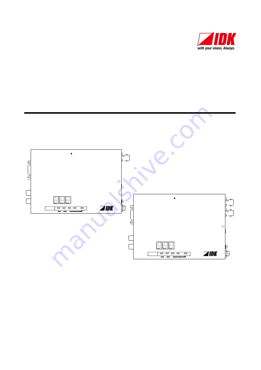
Tx
1 CO AX Tx for HDMI
CO S-T100HD-B
FG
D
C
5
V
3
A
H
D
M
I
O
UT
PU
T
H
D
M
I
IN
PUT
POWER
STATUS
LINK
KEY LOCK
-
+
SET
SIGNAL
HDCP
R
S-2
3
2
C
FG
D
C
5
V
3
A
H
D
M
I
Rx
CO S-R100HD-B
L
A
U
D
IO
O
U
T
PU
T
R
POWER
STATUS
LINK
KEY LOCK
-
+
SET
SIGNAL
HDCP
O
U
T
PU
T
IN
PU
T
1 CO AX Rx for HDMI
O
U
T
PU
T
●
Thank you for choosing our product.
●
To ensure the best performance of this
product, please read this User’s Guide fully and carefully before
using it and keep this manual together with the product for reference as needed.
IDK Corporation


