ICM Controls SC 2210, Installation, Operation & Application Manual
The ICM Controls SC 2210 is a versatile device designed for HVAC systems. To ensure hassle-free installation and operation, make sure to download the comprehensive "Installation, Operation & Application Manual" from our website, manualshive.com, absolutely free. This manual provides step-by-step instructions and valuable insights for optimal product usage.
Share
Download


Reviews:
No comments
Related manuals for SC 2210
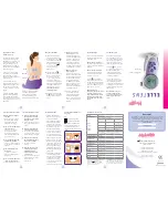
Elle TENS
Brand: Babycare TENS Pages: 2

THERMIC
Brand: wattio Pages: 51

Intellitherm C75
Brand: Fantini Cosmi Pages: 20

T5900
Brand: Venstar Pages: 71

R2001
Brand: REED Pages: 1

MARATHON MM SERIES
Brand: RayTek Pages: 88

T8532OCC
Brand: Entergize Pages: 4

6053051
Brand: DELTA DORE Pages: 11

GTS-TH-V
Brand: Radiant Pages: 2

6110.4ZL
Brand: Everest Pages: 13

DTC-120
Brand: Ringder Pages: 2

Alfanet 95
Brand: VDH Pages: 8

OR80 OT
Brand: Bosch Pages: 28

3H/2C
Brand: Bosch Pages: 24

8-733-944-325
Brand: Bosch Pages: 24

BCC50
Brand: Bosch Pages: 27

OR30 OT
Brand: Bosch Pages: 16

BCC100
Brand: Bosch Pages: 36


