background image

BNX_100_3000_EN   Ed. 08 - 03/2019

EN

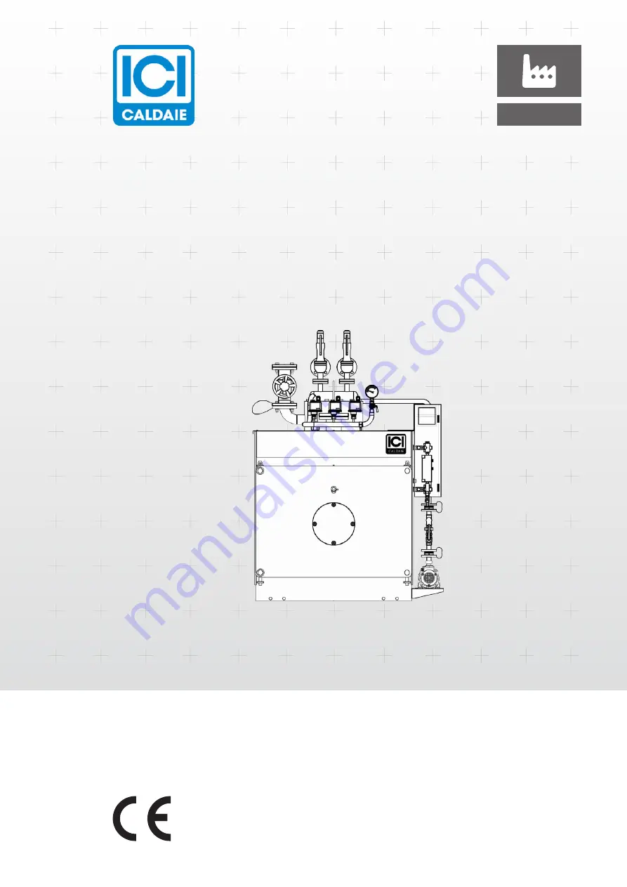
Low-pressure reverse flame steam boiler

BNX

INSTALLATION, USE AND MAINTENANCE MANUAL

Cooke Industries - Phone: +64 9 579 2185    Email: [email protected]    Web: www.cookeindustries.co.nz

Summary of Contents for BNX 100

Page 1: ...3000_EN Ed 08 03 2019 EN Low pressure reverse flame steam boiler BNX INSTALLATION USE AND MAINTENANCE MANUAL Cooke Industries Phone 64 9 579 2185 Email sales cookeindustries co nz Web www cookeindustries co nz ...

Page 2: ... removal 20 Installation room 20 Positioning 20 Room ventilation 21 System cleaning 21 Hydraulic connections 21 Flue exhaust 22 Front door opening 22 Door opening reversal to the right 24 Front door adjustment 25 Turbulator assembly 26 Burner assembly 26 Electrical connections 27 Loading and supply of the generator system 27 Hydrostatic head diagram 28 Water characteristics 29 Frequency of analysi...

Page 3: ...650 BNX 500 86420500 BNX 1400 86421400 BNX 3000 86423000 BNX EXP 0 98 bar BNX EXP 0 98 bar BNX EXP 0 98 bar BNX EXP 100 86420104 BNX EXP 700 86420704 BNX EXP 1700 86421704 BNX EXP 150 86420154 BNX EXP 850 86420854 BNX EXP 2000 86422004 BNX EXP 350 86420354 BNX EXP 1000 86421004 BNX EXP 2650 86422654 BNX EXP 500 86420504 BNX EXP 1400 86421404 BNX EXP 3000 86423004 BNX EXP 0 7 bar BNX EXP 0 7 bar BN...

Page 4: ... during handling and installation Periodically check the condition of the same accessories exclusion of fractures Once installation is completed check the intervention of the safety valve by carrying out a preventive hydraulic test at the PT pressure indicated on the ID plate Make sure the safety level switch is working properly in accordance with the contents of the technical manual supplied with...

Page 5: ...the room by opening doors and windows close the fuel shut off device Perform any technical or cleaning intervention before disconnecting the appliance from the electrical power supply and wearing the Personal Protective Equipment P P E according to Italian Legislative Decree 81 08 Modifying safety or adjustment devices without the boiler manufacturer s authorisation and indications Plug or dimensi...

Page 6: ...refore ensure the generator is properly installed and adjusted and the presence of ventilation openings in the thermal power plant are compliant with the regulations in force IDENTIFICATION Each generator BNX is identified by the following nameplates Boiler body nameplate 1 this plate carries the boiler body main data and is riveted on a special support Assembly nameplate 2 this plate carries the ...

Page 7: ...s stability The BNX steam generators have obtained suitability for liquid and gaseous fuels for the production of low pressure 0 7 0 9 bar 100 to 3000 kg h steam STRUCTURE 1 Electrical panel 2 Adjustment pressure switch es 3 Block pressure switch 4 Pressure gauge 5 1st safety level probe minimum 6 Level adjustment probes start stop 7 2nd safety level probe minimum 8 Level indicator 9 Level indicat...

Page 8: ...20 1920 P mm 1225 1720 2060 2085 2335 2625 2625 2625 2925 3160 3720 3720 P2 mm 820 1170 1510 1510 1760 2010 2010 2010 2310 2515 3015 3015 P6 mm 240 290 280 330 280 330 310 360 310 360 350 400 350 400 370 420 370 420 370 420 420 470 420 470 Øb mm 130 160 180 225 225 280 280 280 280 320 360 360 Øc mm 180 200 250 250 250 300 300 350 350 400 450 450 Attachments Description u m BNX 100 150 350 500 700 ...

Page 9: ...N u m BNX 1000 1400 1700 2000 2650 3000 Effectiverated 1 kW 698 897 1163 1395 1744 2035 Thermalcapacity kW 767 985 1278 1533 1917 2236 Efficiencyat100 ref P C I 1 91 00 91 00 91 00 91 00 91 00 91 00 Pressuredropsonexhaustside mbar 6 0 5 5 7 0 7 5 6 5 7 5 Ratedpressure bar 0 98 0 98 0 98 0 98 0 98 0 98 Totalcapacity l 1400 2010 2280 3020 4240 4240 Capacityatlevel l 1100 1560 1790 2050 3100 3100 Exc...

Page 10: ...rm 4 Alarm s indicator Alarm indicator box see the type below if there are several alarms the display will display them alternately every 4 seconds 5 Alarm silencing key Press to mute the buzzer when a new alarm appears it will switch back on automatically 6 Key to reset the alarms in the memory If signal 2 is not on and the display is flashing alarm s in the memory but not present the button can ...

Page 11: ...mbustion chamber considering also the possible resistance draught of the smoke duct the length of the combustion head must be adequate to the penetration into the combustion chamber provided by ICI and shown in the table the length and shape of the flame must be suitable to the flame inversion combustion chambers The burner manufacturers have this information as they are required by certification ...

Page 12: ...ificate declaration of conformity use and maintenance manual feed pump characteristic curve Machinery Directive 2006 42 EC for liquid fuel burners wiring diagram always housed in the electrical panel m USER OBLIGATIONS Check which pressure equipment commissioning and use regulations are in force in the country of use FIRE PREVENTION Refer to the Regulations in force in the Unit Installation Countr...

Page 13: ...ed and free to move is connected to the index by a toothed sector lever system The pressure gauge is mounted on a three way valve that allows performing the following operations Communication between generator and pressure gauge normal operating position Communication between pressure gauge and the outside position needed to purge the siphon Communication between generator pressure gauge and sampl...

Page 14: ...valve so as not to harm people or damage property Typical suggested scheme Interception valves must not be provided The exhaust pipe must be designed in such a way that any low temperatures do not create ice that ob structs the outlet N B Bracket at no more than 1 m away m IMPORTANT The operation of the safety valves is sensitive to pressure losses that occur in the drain conveying pipe during the...

Page 15: ...imum one of the pressure transmitter but always lower than the opening pressure of the safety valve The safety pressure switch intervenes in case of steam pressure regulator failure adjustment pressure switch or pressure transmitter and permanently stops the burner 1 Main shaft 2 Main spring 3 Differential shaft 4 Differential spring 5 Reset spring 6 Activation lever 7 Bellows 8 Pressure connectio...

Page 16: ...the purge valve for a few seconds and close it again If the water disappears and then quickly returns to the starting point with large swings it can be assumed that the level works well Whereas if the water slowly returns or stops at a different point from the previous it means that one of the communications is obstructed to ascertain which of the two and to try purging it close the steam valve le...

Page 17: ... one longer 2 to start the pump and one shorter 1 to stop it connected to a single adjustment relay in the control panel Burner stop for low level it is managed with two probes 3 and 4 of the same length inserted in the generator and connected to two separate adjustment relays in the control panel They generate a burner stop if the water level drops below the minimum limit allowed 4 1 5 2 3 Probes...

Page 18: ...ing documentation declaration of conformity use and maintenance manual safety valve certificate with declaration of conformity and use and maintenance manual feed pump characteristic curve electrical diagram m IMPORTANT The instruction manual is an integral part of the appliance and so MUST be carefully read before installing and commissioning the generator carefully stored for future consultation...

Page 19: ... 500 BNX 3600 a ATTENTION Do not expose the packed product to direct sunlight FILM REMOVAL The boilers can feature the following types of protective films a ATTENTION Remove the PROTECTIVE FILM if any After handling and after having installed all components BEFORE STARTING THE BOILER The generated heat makes it impossible to remove the film The film exposure to direct sunlight makes it impossible ...

Page 20: ...e of installation must be arranged around the boiler the boiler can be installed inside an outdoor prefabricated heating plant room compatibly with the dimensions of the supplied boiler model and in compliance with the Legislation in force in the place of installation COMPULSORY request upon order placing A P2 see Size and fittings m IMPORTANT A space is necessary at the front of the generator at ...

Page 21: ...es have been connected to a drain well in order to avoid that in case of intervention the rooms are flooded Make sure that the water and heating system pipes are not used as earthing point of the electrical system The air must be filtered with a 25 μm mesh m IMPORTANT ICI CALDAIE S p A is not liable for any harm to people animals or property damage caused by errors in the choice of components or i...

Page 22: ... 1 9 2 3 4 6 7 8 5 8 Dx Sx BNX 100 2650 BNX 100 2650 BNX 3000 BNX 3000 1 m IMPORTANT The door should be secured before performing the opening inversion and adjustment operations a DANGER IT IS DANGEROUS TO UNSCREW the ring nuts 8 located on hinge side This could cause the detachment of the door with possible severe damages to persons and property Dx 8 Cooke Industries Phone 64 9 579 2185 Email sal...

Page 23: ...old the door Dx Sx 8 1 Proceed as follows to reverse the opening direction of the door loosen drilled ring nut 1 and socket ring nut 8 Dx Sx 1 8 loosen locking nuts 2 present on tie rods and release the conical washers 4 Sx 2 4 Cooke Industries Phone 64 9 579 2185 Email sales cookeindustries co nz Web www cookeindustries co nz ...

Page 24: ...ed in the following paragraph FRONT DOOR ADJUSTMENT a DANGER Incorrect door adjustment with consequent damage to people and property voids the warranty conditions 1 2 3 6 4 5 7 Dx Sx VERTICAL ADJUSTMENT To make the adjustment with the door ajar loosen the counter nuts 1 of the hinge units act on the adjustment nuts 2 to lift or lower the door by centring the gasket on the stop plate then block the...

Page 25: ... to the stop plate naturally returns remaining ajar This is to ensure the hinge side fume seal a DANGER THERE MUST BE NO FLUE GAS LEAKS TURBULATOR ASSEMBLY To assemble the turbulators supplied with the boiler open the door and insert the turbulators completely into the smoke pipes until they penetrate by at least 100 m a DANGER The turbulators have very pointed and sharp ends Therefore wear suitab...

Page 26: ...the gap 1 P6 5 Øb 4 3 1 1 Burner 2 Flange 3 Gasket 4 Door 5 Thermoceramic material 1 2 3 4 ELECTRICAL CONNECTIONS The generators are equipped with electrical panel IP 55 protection rating complete with all connections to the various generator components already made in the factory The panel model is determined by the version of the ordered generator and the wiring diagram specific and detailed is ...

Page 27: ...pipe and on the features of the pump itself refer to the pump manual a ATTENTION The oxygen dissolved in the water corrodes the boiler Refer to the maximum allowed values indicated in the relevant section of the technical manual Follow the table below to avoid pump cavitation problems DEGASSER TYPE Water supply temperature C Head on the intake metres Atmospheric degasser 60 1 70 2 80 3 90 4 5 0 5 ...

Page 28: ...e a With copper alloys in the system the pH value must be kept within 8 7 and 9 2 b With a softened water pH value 7 0 the pH of the generator water should be provided according to table 5 2 c At operating pressure 1 bar a maximum total hardness of 0 05 mmol l must be acceptable d Instead of respecting this value with intermittent operation or operation without deaerator in case of agents forming ...

Page 29: ...t can be applied under AVT conditions treatment with volatile chemicals feed water pH 9 2 and generator water pH 8 in this case the conductivity of the generator water is 5 μS cm d If treatment with coordinated phosphate is used considering all other values higher concentrations of PO4 are acceptable e Organic substances are generally a mixture of various different compounds The composition of suc...

Page 30: ...e steam generator place the main switch at ON and electrically power the control panel electrically power the pump briefly activating the selector and check that the rotor rotates freely for the three phase version that the rotation direction is correct indicated at the back of the motor place the pump selector at AUT and check that there is no consent to start the burner before the water has reac...

Page 31: ... the stop periods The operations to be carried out to store the generator correctly essentially depend on the duration of the downtime When the generator needs to be stopped for long periods dry storage can be done When the stops are for short periods or when the generator is used as a spare and must start running in a short amount of time a wet storage can be made In both cases the operations des...

Page 32: ...the drain valves replace them if necessary PERIODIC VERIFICATIONS The frequency of verifications is shown in the table It MUST be strictly observed Observation and tests 6 hours 1 day 1 week 1 month 3 months 6 months 12 months Safety valves O T 9 Level indicators T 4 TDS BWD Unloading devices if present T 5 Shut off valves O T 10 Water load control devices O Low level protection devices if present...

Page 33: ...d by qualified personnel T 15 Bench check of the safety devices Verifications must be performed by qualified personnel a ATTENTION The electronic level relays inside the electrical panel must be replaced after 8 years of operation as they have reached the end of their life span METHODS FOR CHECKING THE SAFETY DEVICES CHECKING OF THE MINIMUM LEVEL SAFETY LEVEL SWITCHES Stand in front of the electri...

Page 34: ...urces of danger pertaining to the feed water It is necessary to remove the deposits through mechanical or chemical action and use suitable tools to ensure that the actual thickness of the internal parts is not affected by corrosion Any pockmark or other type of corrosion must be scraped and cleaned with an iron brush until the metal is exposed Leaks between all fume pipes and tube sheets must be e...

Page 35: ...difference between the collection vessel level and the pump insufficient in relation to the water temperature Pump intake filter cleaning Reduce resistance of the duct between collection vessel and pump by increasing the passage section Pump rotation direction Invert one of the phases three phase pump Burner always on Incorrect connection to the electrical panel See the wiring diagram Faulty level...

Page 36: ...drostatic head in suction water supply temperature pump connection disconnection from the level control probes OVERHEATING DUE TO THERMAL INERTIA Position of water minimum level 100 mm above the highest point of the heated surface Calculation ensuring that the evaporation caused by refractory material thermal inertia does not uncover the highest point of the heated surface OVERHEATING DUE TO SCALE...

Page 37: ...of contained fluid refer to the user s manual POWER SUPPLY A mains voltage control device has been inserted inside the electric system voltage asymmetry phase presence phase sequence Make sure that the panel power supply complies with the indications given in the attached wiring diagram ELECTRIC PANEL ACCIDENTAL OPENING Door lock connected to main switch Voltage adhesive label Inner parts can be a...

Page 38: ... Make sure that hydraulic connections are duly joined together Check the correct connection of electric parts Perform a correct chimney fastening Check generator correct operation FAILING TO CARRY OUT MAINTENANCE Carry out a periodical preventive maintenance and any component repair or replacement operations according to the indications set forth in the Technical Manual and anyway for the cases no...

Page 39: ... with the indications set forth in the manual FIRE The plant room must be arranged in compliance with the fire protection regulations in force in the country of installation Check that body and accessories are intact and not damaged after the fire UNIT POOR MANAGEMENT The operator must meet the requirements provided by the prevailing standards in the country of installation The user is anyway obli...

Page 40: ...ta of your appliance and system by completing the indicated spaces Once registered authenticate your e mail address by clicking on the link that will be sent by e mail to the provided inbox An additional e mail will then be received with the credentials to access all services specifically developed by ICI CALDAIE S p A for those who will register their boiler through the QR Code Registration entit...

Page 41: ...Notes 41 7 Notes Cooke Industries Phone 64 9 579 2185 Email sales cookeindustries co nz Web www cookeindustries co nz ...

Page 42: ...Notes 42 Cooke Industries Phone 64 9 579 2185 Email sales cookeindustries co nz Web www cookeindustries co nz ...

Page 43: ...Notes 43 Cooke Industries Phone 64 9 579 2185 Email sales cookeindustries co nz Web www cookeindustries co nz ...

Page 44: ... Campagnola di Zevio Verona Italy Via G Pascoli 38 Phone 39 0458738511 Fax 39 0458731148 info icicaldaie com www icicaldaie com Cooke Industries Phone 64 9 579 2185 Email sales cookeindustries co nz Web www cookeindustries co nz ...

Reviews: