background image

R4

SAFETY NOTICE

PLEASE READ THIS ENTIRE MANUAL BEFORE YOU INSTALL AND USE YOUR NEW BOILER.  FAILURE TO FOL-
LOW INSTRUCTIONS MAY RESULT IN PROPERTY DAMAGE, BODILY INJURY, OR EVEN DEATH.

FOR USE IN THE U.S. AND CANADA.  SUITABLE FOR INSTALLATION IN MOBILE HOMES

IF THIS HARMAN PELLET BOILER IS NOT PROPERLY INSTALLED, A HOUSE FIRE MAY RESULT.  FOR YOUR SAFETY,
FOLLOW INSTALLATION DIRECTIONS.

CONTACT LOCAL BUILDING OR FIRE OFFICIALS ABOUT RESTRICTIONS AND INSTALLATION INSPECTION
REQUIREMENTS IN YOUR AREA.

CONTACT YOUR LOCAL AUTHORITY (SUCH AS MUNICIPAL BUILDING DEPARTMENT, FIRE DEPARTMENT, FIRE
PREVENTION BUREAU, ETC.) TO DETERMINE THE NEED FOR A PERMIT.

CETTE GUIDE D'UTILISATION EST DISPONIBLE EN FRANCAIS. CHEZ VOTRE CONCESSIONNAIRE DE HARMAN STOVE
COMPANY.

SAVE THESE INSTRUCTIONS

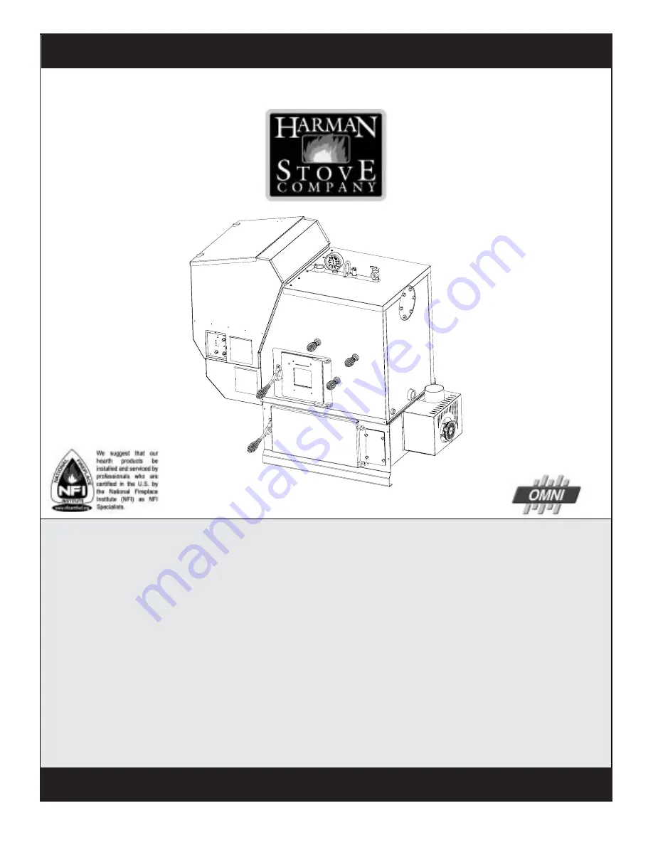
The Harman PB 105 Pellet Boiler

Installation & Operating Manual

“Ce manuel est disponible en Français sur demande”

R1

Tested by
OMNI-Test Labortories

Summary of Contents for PB 105

Page 1: ...LOW INSTALLATION DIRECTIONS CONTACT LOCAL BUILDING OR FIRE OFFICIALS ABOUT RESTRICTIONS AND INSTALLATION INSPECTION REQUIREMENTS IN YOUR AREA CONTACT YOUR LOCAL AUTHORITY SUCH AS MUNICIPAL BUILDING DEPARTMENT FIRE DEPARTMENT FIRE PREVENTION BUREAU ETC TO DETERMINE THE NEED FOR APERMIT CETTEGUIDED UTILISATIONESTDISPONIBLEENFRANCAIS CHEZVOTRECONCESSIONNAIREDEHARMANSTOVE COMPANY SAVETHESEINSTRUCTIONS...

Page 2: ......

Page 3: ...ge Pressure Relief Valve Aquastat Well 1 1 4 FMPT Supply 1 1 4 FMPT Return Ash Door Firebox Door Access Cover To Hopper Swing Plate Knob Access Cover To Secondary Ash Chamber Heat Exchanger Clean Blank Cover Removed w D Hot Water Opt Vent Pipe 1 2 FMPT Boiler Dr not shown Viewing Glass PB 105 Parts PB105 Parts ...

Page 4: ...List Options 35 Warranty 36 Testing Label 37 Quick Reference Start Up Back Cover Please read this entire manual before you install and use your new boiler Failure to follow instructions may result in property damage bodily injury or even death SAVE THESE INSTRUCTIONS Harman Stove Company 352 Mountain House Road Halifax PA17032 Table of Contents ...

Page 5: ...es QTY 5 Removed w Domestic Hot Water Coil Option Shown Here MPT Boiler Drain Not Shown Temperature Pressure Gauge Aquastat Well Pressure Relief Valve Blank Cover Heat Exchanger Cleanout Rod Handles Access Cover To Secondary Ash Chamber Remove Cover to access nuts to fasten Flue Tunnel Weldment to the Ash Chamber Flue Tunnel Weldment ESP Probe Combustion B He Thumb Screws 3 Firebox Ash Door Handle...

Page 6: ...mber base Fasten the 4 nuts and lock washers provided to the studs by removing the access cover on the secondary ash chamber Step 2 Place the combustion motor onto the flue tunnel weldment and tighten the 3 wing screws provided Step 3 Insert the Exhaust Sensing Probe ESP into the 1 8 hole provided on the flue pipe stub Fasten with the 1 8x1 2 TEK screw also provided ESP will be taped to the sheet ...

Page 7: ... the 1 2 MPT temperature pressure gauge in fitting as shown 7 Locate and install outside air temperature sensor Location of this sensor should be on the north side of the home or building and out of direct sunlight Use the cat cable supplied with the boiler to attach sensor to the terminals located on the hopper Place at the back side just above and to the right of the main power connection box Th...

Page 8: ...er type L or PL venting system Be sure to inspect and clean exhaust venting system frequently WheninstallingthePB105inamobilehomeseveral requirementsmustbefollowed 1 The unit must be bolted to the floor 2 The unit must be connected to outside air 3 Floor protection and clearances must be followed 4 Unit must be grounded to the metal frame of the mobile home ...

Page 9: ...lcenter lineoftheregulator 1 I The clearance to service regulator vent outlet mustbeaminimumof6feet 1 J The clearance to a non mechanical air supply inlet to the building or the combustion air inlet to any otherappliancemustbeaminimumof48 1 K The clearance to a mechanical air supply inlet mustbeaminimumof10feet 1 with outside air installed 6 feet L The clearance above a paved sidewalk or a paved d...

Page 10: ...10 Venting Fig 3 ...

Page 11: ...n Fig 5 Venting Use 4 pellet vent pipe to vent your PB105 A combustion blower is used to extract the combustion gases from the firebox This creates a negative pressure in the firebox and a positive pressure in the venting system as shown in Fig 4 The longer the vent pipe and more elbows used in the system the greater the flow resistance Because of these facts we recommend using as few elbows as po...

Page 12: ...has accumulated 3mm or more it should be removed to reduce the risk of a chimney fire The PB105 Boiler may be used and installed into an existingmasonaryorClassAmetalchimney Certain Canadian and Local Codes may require that the chimney be fully relined It Can Not be installed in a chimney serving another appliance The chimney should be cleaned and or inspected be foreinstallation Venting Installat...

Page 13: ...xcept for several small tabs There is also a filler plate screwed to the inside to cover the top of the hole after the OutsideAir Pipe has been installed This will allow for removal of theFeederCoverwithoutdisconnectingtheOutsideAir Pipe See Fig 7 Only metal Intake Flex should be used for the OutsideAirSupplyconnection Only a screened or rodent protected OutsideAir Intakecovershouldbeusedasanoutsi...

Page 14: ...otected with an in line fuse rated at 6 AMP This boiler should never be powered by the use of an extension cord The recommended high and low voltages are 130 V A C 60 Hz maximum high voltage and 113 V A C 60 Hz minimum low voltage The furnace will continue to operate at voltages as low as 105 V A C although it can not be guaranteed that automatic ignition will occur NOTE If other sources of electr...

Page 15: ...15 Installing Duct Installation ...

Page 16: ... fuel to the other without requiring the manual adjustment of any controls or components other than the thermostats 4 Be compatible with the operation of a service water heating coil within the original boiler without bypassing the operation of the solid fuel boiler 5 Have provision for preventing or adequate water capacity within the boiler to prevent damage to the boiler from loss of circulation...

Page 17: ...17 Installation ...

Page 18: ...18 Installation ...

Page 19: ...19 Installation ...

Page 20: ...Dependingontheamountofverticalrise itmay not be possible to get a low draft reading in this range In this case a maximum low draft of 55 is acceptable Theadjustmentscrewisthroughthesmallholetothe rightoftheIgniterLight SeeFig 10 AdjustedLowDraft is __________ IWC Don t forget to turn the feed adjuster back to 4 Draft Bolt Location Viewing Window Air wash Slot Fig 9 Test Low Draft Adjustment Pot Fi...

Page 21: ... 205 Degree F Igniter Light Indicates power to the igniter Lighting Mode Selector Switched between Auto and Manual lighting Mode Selector Min Temp Dial Used to turn the boiler on or off and set the desired minimum operating temperautre of the boiler Status light error messages 1 Blink Indicates control board self diagnostic failure This requires a manual reset by cycling the main power off for a f...

Page 22: ...condary ash chamber area and also in the venting system both of which could cause damage in these areas One Exception to this would be summertime operation with a domestic hot water coil option The boiler water tempera ture could be maintained at a lower temperature since there would be no load from the heating system and recovery would be quick NOTE If the system is run at the lower temperature s...

Page 23: ... rise of the OA Degree Min set 150 Water Temp Example 1 Max set 185 Min set 120 Water Temp Degree OAT 65 120 60 125 55 130 50 135 45 140 40 145 35 150 30 155 25 160 20 165 15 170 10 175 5 180 0 185 OAT 65 150 60 150 55 150 50 150 45 150 40 150 35 150 30 150 25 155 20 160 15 165 10 170 5 175 0 180 No change in boiler temperature after reaching minimum setpoint temp Example 2 Max set 180 Pellet Boil...

Page 24: ...feeder NOTE To minimize the amount of stress placed on the hopper swing plate hinges opening of the hopper swing plate should be done when the hop per fuel level is low whenever possible Scrape burnpot to remove any carbon build up that may have occurred Scraping can be done while in operation if performed through the firebox door opening 3 Fill hopper with pellets When filling the hopper check fo...

Page 25: ...rent pellets set the feed adjuster to 4 This is a conservative number and will prob ably need to be increased if maximum BTU output is desired After you know a feed rate setting that works well for your application use that setting 7 Turn the MAX TEMP Dial on the control board to the desired temperature This setting must always be higher then the MIN TEMP setting Operation 6 Flip the Igniter Switc...

Page 26: ...s are kept the more efficient the boiler will be NOTE Do not burn garbage gasoline naphtha engine oil or other inappropriate materials in the PB105 Storepelletsinthemanufacturer swrapping until needed to prevent pellets from absorbing moisture Do not store fuel within the appliance installationclearances orwithinthespacerequired for fueling ash removal and other routine maintenance operations Oper...

Page 27: ...ve the MIN TEMP setting Once the fire is well estab lishedtheMAXTEMPdialcanremainonanytemperature settingdesired NOTE When the Switch is set to Manual igniter position the boiler will function as in auto igniter except the fire will not be allowed to go out It will only be allowed to go to a minimum burn rate between the times the aquastat is calling for heat This rate is about 1 1 pound of fuel p...

Page 28: ... Thisareaonlyneedstobecleanedtwiceaheatingseason unlessexcessivebuildupisnoticedduringscheduledcleanings There is a cover on the front of the burnpot to gain access to the air chamber and igniter The cover is held into place by two thumb screws Loosen the thumb screws and remove the cover See Fig 19 The air chamber can be cleaned of any ash thathasfallenthroughtheholesduringoperationandcleaning Al...

Page 29: ...wiselocallydispersed theyshouldberetainedintheclosedcontaineruntilallcinders havethoroughlycooled Soot and Flyash Formation and Need for Removal The products of combustion will contain small particlesofflyash Theflyashwillcollectintheexhaustventing system and restrict the flow of the flue gases Incomplete combustion such as occurs during startup shutdown or incorrect operation of the room heater w...

Page 30: ...ocated inside the burnpot Open firebox door and vaccum ash from ledges and ash deflector You can also clean the firebox door viewing glass using a typical glass cleaner and soft cloth Heat Exchanger Cleanout Rod Handles Heat Exchanger Tube Ash Door Firebox Door Secondary Ash Chamber Access Plate Fines Cleanout Cover Firebox Wall Heat Exchanger Cleanout Rod Handles Heat Exchanger Tube Ash Door Fire...

Page 31: ...4 NOTE The ESP probe sensing tip extends into this same area CARE MUST BE TAKEN NOT TO DAM AGE THE ESP PROBE DURING CLEANING Bending of the ESP probe will make it difficult to remove if it should become necessary See Fig 24 Clean the boiler blower plate sealing overlap See Fig 24 Make sure there are no fly ash buildups that may block the easy flow of flue gasses into the combustion blower inlet ho...

Page 32: ... HAS GONE OUT 1 No pellets in hopper 2 Draft setting is too low 3 Something is restricting fuel flow 4 Feed motor or combustion blower has failed 5 Power failure or blown fuse SMOKE IS VISIBLE COMING OUT OF VENT 1 Air fuel ratio is too rich A Feed rate too high B Draft too low caused by a gasket leak LOW HEAT OUTPUT 1 Feed rate too low 2 Draft too low because of gasket leak 3 Poor quality or damp ...

Page 33: ...33 Feeder Parts ...

Page 34: ...er 1 4 AMP Auger motor 7 AMP Igniter element 2 3 AMP Control board 05 AMP Approximate operating wattage 2 KWH BTU Input Range 0 9350 to 113 900 0 BTU if system is satisfied Min burn 1 1 pound per hour Max burn 13 4 pound per hour 8500 btu lb Electrical 120 VAC 60 Hz Combustion blower 1 4 AMP Auger motor 7 AMP Igniter element 2 3 AMP Control board 05 AMP Approximate operating wattage 2 KWH ...

Page 35: ...35 Wiring Diagram Wiring Diagram ...

Page 36: ...E TEMPGAUGE 3 10 935111 WELL 3 20 00607 THERMOSTATEXTENSION 3 20 00744 THERMISTERPROBE 3 20 02583 2 PAIRTWISTEDCAT3CABLE 100FT 3 20 05630 CIRCUITBOARD 3 20 09302 FEED MOTOR 6 RPM 3 20 09302B FEEDMOTORBLADE 3 20 3433 PRESSURESWITCH 3 20 49447 6AMPFUSE 3 20 502221 COMBUSTIONBLOWERBLADE 3 20 72180 AQUATEMPSENSOR OUTDOORAIRTEMP SENSOR 3 20 72181 OUTDOORAIREXTENSIONTCP 3 20 72195 WIRINGHARNESS 3 21 086...

Page 37: ...vered Damage and or repairs including but not limited to remote controls filters fuses knobs glass ceramic brick panels ceramic fiber afterburners combustion packages door packing tile ceramic log sets paint batteries or battery backups and related duct work are not covered Also excluded from this warranty are consumable or normal wear items including but not limited to flame guides grates coal ba...

Page 38: ...Testing Label 38 ...

Page 39: ...NOTES 39 ...

Page 40: ...urn Feed Adjuster back to the 4 setting 8 Turn the MAX TEMP dial to the desired temperature 9 Turn MIN TEMP dial to the desired settings 10 Flip the igniter switch to Auto The boiler will ignite if the temperature of the boiler water is less than the temperature set on MAX TEMP dial See the section on Operation for information about Manual Lighting and Emergency Power See the section on Maintenanc...

Reviews: