Husqvarna 333RB Mark II, Workshop Manual
The Husqvarna 333RB Mark II is a powerful and reliable workshop tool designed for professionals. If you're in need of a detailed manual to guide you through maintenance and operation, you can download the free Workshop Manual from manualshive.com. This comprehensive manual ensures seamless performance and efficient use of this exceptional product.
Share
Download


Reviews:
No comments
Related manuals for 333RB Mark II
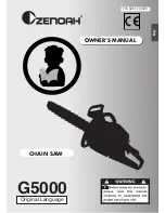
G5000
Brand: Zenoah Pages: 15

Solo CS 4235
Brand: AL-KO Pages: 500

721-340
Brand: Meec tools Pages: 132

468419
Brand: Lux Tools Pages: 42

45.016.37
Brand: Bavaria Pages: 108

45.018.18
Brand: Bavaria Pages: 124

SP 510
Brand: Stiga Pages: 2

GS 371
Brand: EMAK Pages: 214

MasterCut5700W
Brand: MALTEC Pages: 59

CS-346
Brand: Echo Pages: 28

CS-355T
Brand: Echo Pages: 36

UC003G
Brand: Makita Pages: 24

DCS232T
Brand: Makita Pages: 20

HCS5130CB
Brand: Fairmont Pages: 16

DCS 43
Brand: Makita Pages: 24

BUC300
Brand: Makita Pages: 24

DCS 340
Brand: Makita Pages: 60

BUC250
Brand: Makita Pages: 128


