Hunter Stoves Telford Inset 20DB CVWSTI08DBFM, Instructions For Installation/Operating/Maintenance/Servicing
Looking for Instructions For Installation/Operating/Maintenance/Servicing of your Hunter Stoves Telford Inset 20DB CVWSTI08DBFM? Download the manual for free from manualshive.com to ensure proper care and usage of your stove. Simple and easy step-by-step guidance to help you get the most out of your product.
Share
Download


Reviews:
No comments
Related manuals for Telford Inset 20DB CVWSTI08DBFM
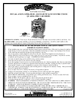
3100 Series
Brand: Quadra-Fire Pages: 32

ALDERLEA T5 LE
Brand: Pacific energy Pages: 32

KIYOMI
Brand: Zibro Pages: 12

C 850W
Brand: Contura Pages: 16

Ellesmere EC5W
Brand: AGA Pages: 17

COMBO COAL & WOOD STOVE
Brand: New Buck Corporation Pages: 35

VOGELZANG VG1820
Brand: United States Stove Pages: 40

Ashley AW3200E-P
Brand: United States Stove Company Pages: 40

Ashley AP60
Brand: United States Stove Company Pages: 48

DOGE3 PLUS
Brand: Cadel Pages: 48

193E
Brand: Cadac Pages: 5

Stove with 3,6 kW PnP
Brand: Karibu Pages: 68

1600S
Brand: Seefire Pages: 10

SF 3500A
Brand: Harman Stove Company Pages: 20

PARiZHAR
Brand: VVD Pages: 44

italy termo dsa
Brand: Nordica Pages: 68

219
Brand: Kenyon Pages: 12

EA1105J
Brand: allen Pages: 10


