background image

---- KRONOS100 integrated surveying GPS receiver 


Operation Manual 


Summary of Contents for KRONOS100

Page 1: ... KRONOS100 integrated surveying GPS receiver Operation Manual ...

Page 2: ... 11 CHAPTER III OPERATION IN THE FIELD 13 3 1 MAIN INTERFACE 13 3 1 1 Initialize interface 13 3 1 2 System interface 13 3 2 OPERATION IN THE FIELD 18 3 2 1 AUTO Mode 18 2 2 2 MAN Mode Collecting 20 2 2 3 LED mode 22 CHAPTER IV KRONOS100 DIFFERENTIAL GPS SYSTEM 23 4 1 WORKING MODE 23 4 2 THE INITIALIZATION INTERFACE 23 4 3 STEPS OF FIELD WORK 23 4 4 DYNAMIC POST PROCESSING SOFTWARE 28 4 4 1 Softwar...

Page 3: ...3 B STANDARD PACKING 39 ...

Page 4: ...EDs will indicate when you select LED mode LED mode please refer to chapter III SAT is the satellite indicator LED These are two keys on receiver one is power key and another is S key the function of which is to communicate with controller For initial connection between controller with receiver press S key once then press any button on controller to establish connection between receiver and contro...

Page 5: ...ium batteries It can last 7 5 hours continuously and needs five hours to recharge Figure1 3 lithium battery Installing the battery 1 Open the cover of batteries slot see the following figure Figure 1 4 open the cover 2 Install the batteries see figure 1 4 Please push this button towards to bottom ...

Page 6: ...he LED will display red When batteries are fully charged the LED will display green If the charger does not connect with battery the LED is also red Figure 1 5 Chargers 1 2 3 Tribrach plummet KRONOS100 GPS receiver uses standard optical tribrach plummet Figure1 6 tribrach plummet ...

Page 7: ...igure 1 7 communication cable 1 2 5 Soft bag KRONOS100 soft bag is a durable soft casing to carry and store the KRONOS 100 receiver Figure 1 8 Soft bag 1 3 Software of KRONOS100 GNSS Survey System A Firmware software This is the firmware software used to record raw data in the field B Downloading software KRONOS STATIC MANAGER It is used to download data from receiver to computer and to register c...

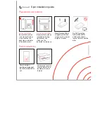
Page 8: ...8 Figure 1 9 post processing software ...

Page 9: ...rveying way or the equivalent way You can also set some level united surveying points in order to offer geoid s information 4 In order to observe and level united survey we often set GPS net points at a clear and easy arriving field 5 We often distribute some well eyeshot azimuth points around GPS net to ensure united survey direction The distance from azimuth to observation station should be more...

Page 10: ...a closed graph so it has a bad checking ability and consistency The advantage of this net is that it only needs two receivers the work is very simple so it is mostly used in the quick surveying as quick static orientation and kinematical orientation This working mode is widely used in project layout border surveying and GIS surveying etc Figure 2 4 star net 2 3 Working range The accuracy of satell...

Page 11: ...nna That is an inclined height Please refer to fig 2 5 Fig2 5 Measuring antenna height We use a formula to calculate antenna height H h R h 2 0 2 0 2 3 h is the inclined height that measure from point on the ground to the waterproof loop of antenna R 0 is the radius of antenna h0 is the distance from antenna phase center to the middle of antenna H is the calculation result We usually measure anten...

Page 12: ...ainframe please be careful 4 Please ensure that receiver should be used once every three month Otherwise the data stored in the EMS will be lost and when you use the receiver next time the receiver will take a long time to initialize ...

Page 13: ...eceiver can evaluate if the condition meets the requirement and then auto enter the collection status At the same time you can see satellite ephemeris and distribution b MAN mode This mode needs you to estimate if the collecting condition meets the requirement which asks for PDOP less than 6 and in the 3D status you can input point name and period of time number to enter the collecting state c LED...

Page 14: ...048K which means the rest EMS memory is about15 6M Power system and battery showing It shows that how much power is used c Function key If you want to use function key please select the key on the controller For example select F1 to enter the File menu The introduction of every function key is as follows 1 Press F1 to enter file interface see fig 3 3 F1 F2 F3 F4 Fig 3 3 second interface of file Yo...

Page 15: ... Press F3 to change the track times which is used for Stop and go function After you finish all settings press F4 to confirm the setting will be saved Special notice If several receivers are working at the same time please set their mask angle and collecting interval as the same 3 Press F3 to enter survey interface see fig 3 5 F1 F2 F3 F4 Fig 3 5 second interfaces of measure It includes five subme...

Page 16: ... number of time period of collection and antenna height Point name please input four characters the name should be as four characters Number of period of time this is to select the surveying period for control point it requires to input the same file name and different period number before you move the control point Antenna height the height of receiver The method is to survey from point on the gr...

Page 17: ...ct the characters segment from A to G with key F3 2 Use F1 to select the letter G from the above characters segment thus character G is inputted 3 Use key F2 to move the cursor 4 Repeat the steps until input the whole name GPS1 5 Press F4 to finish this operation When the cursor moves to period of time input and antenna height input input them according to the way above press F4 to confirm it and ...

Page 18: ... estimate the orientation status and the PDOP value You do not need make any operation the software will enter the data collect status when PDOP meets the requirement You can see the increasing time in the right side which means KRONOS100 mainframe is logging the GPS data You can name the logging data or the software will set the default name as The file construction is set according to collecting...

Page 19: ... logging it but in MAN mode you should input the point name and press the key to start log date 3 End logging data Firstly you should end to log the data before you power off the receiver Please refer to figure 3 11 when the time is enough you can press F4 to end logging 4 Power off receiver 1 Use controller to operate the receiver back to the main interface and long press PWR key on receiver to t...

Page 20: ...l you confirm that the receiver status meets the required condition which is PDOP less than 6 and in 3D status When conditions are satisfied press F3 to enter data collecting interface see fig 3 15 2 Name a logging file When conditions are satisfied press F3 to enter file name input interface see fig 3 12 When you finish the input of file name number of period of time and antenna height press F3 t...

Page 21: ...21 3 Exit data logging The operation is the same with AUTO mode F1 F2 F3 F4 Fig 3 14 manual interface F1 F2 F3 F4 Fig 3 15 measure interface ...

Page 22: ...ry simple When you enter this mode the LCD screen will auto shut off you can only view the satellite and collecting status according to the LED see fig 3 16 Fig 3 16 mainframe The instruction of indicator LED can be found in 3 1 1 In the LED mode you can press any key to activate display screen and enter AUTO mode ...

Page 23: ...tional Default 5s must be observed at one point and the survey process of GO AND STOP is finished here After working in the field you should download the data from receiver to PC Then use KRONOS PROCESSOR after processing the coordinates result will be output directly and all the tracking line will be displayed Operation range 100km Positioning accuracy 1m 4 2 The Initialization Interface Press Po...

Page 24: ...0 Base enters data collection status KRONOS100 Rover can begin to collect data in the survey area Select tracking mode on the initial interface Fig 4 1 press F4 to enter KRONOS100 Rover data collection status F1 F2 F3 F4 Fig 4 4 KRONOS100 Rover setting interface Functions of keys F1 To set collection interval time The default interval is 5 seconds means the epoch of record is 5 seconds F2 To set m...

Page 25: ...shown as figure 4 2 2 Press F2 SET shown as following set the interval time mask angle and track time then Press F4 OK to return the former interface figure 4 2 F1 F2 F3 F4 Fig 4 5 setting interface 3 When the condition is satisfied please press F3 MEAS shown as following picture you will see some information Such as satellite PDOP value and so on F1 F2 F3 F4 Fig4 6 Status interface Note the colle...

Page 26: ...t will pop the picture 4 7 input FILE NAME and TRAGET HT F1 F2 F3 F4 Fig4 7 point setting interface 5 After setting point name and height press F3 to enter track interface shown as Fig4 8 Check the satellite status such as Nav mode PDOP etc F1 F2 F3 F4 Fig 4 8 Track interface ...

Page 27: ...o survey and follow the 5 and 6 steps above In same surveying area no need to move the KRONOS100 Base Special Tip 1 For ensuring survey accuracy please make sure receiver is fixed when initializing and please make sure your pole is level when collecting Don t shake the mainframe 2 Please note the value of cycle slip on the interface when colleting If the value of cycle slip is too big more than 07...

Page 28: ... calculates at a high speed 2 Software use introduction Basic steps New job Fill in each item in the dialog box especially must select the coordinate system and projection zone Add observation data Import the KRONOS100 Base and Rover data of DAT to the software at the same time Post differential processing Input the known coordinate value of Base get the report after real time processing Report ou...

Page 29: ...alculate the four parameters calculate the four parameters by two points then import the parameter setting to use in the processing 3 Software use model This chapter use example data to introduce the specific operation Before use this software it requires to get a register No the way of registration is the same as static processing software Both Base file 8464273D DAT of field surveying data and R...

Page 30: ...llowing figure 4 14 Fig 4 14 Differential data From the above figure the data has been imported into the program 3 Input the known coordinate of KRONOS100 Base station Click Station coordinate from Input menu and a dialog box comes out shown as below Fig 4 15 Input known coordinate The default coordinate value of the software is the single point geodetic coordinate set in the Project Setting but w...

Page 31: ...urveying point are available here which can be printed on the current form If want to make further use of the report export the report in the format of file in order to import the surveying data into other software Select Track report from Report coming out a dialog box Select an output path for the report file You can select different output result from this menu ...

Page 32: ...s follows This software can be used to download raw data Device setting Register and Firmware upgrade for KRONOS100 Note Before connect KRONOS100 with PC via USB power off KRONOS100 first 5 1 1 5 1 3 5 1 1 Import record data After connect well open the receiver disk you will see the DAT file ...

Page 33: ...SSOR 5 1 2 Device Setting Click Device Setting then it will pop windows as following Interval recording interval for data Cut angle mask angle for tracking satellites Time zone local time zone Sample time recording times for one point 5 1 3 Register In the main interface click Register ...

Page 34: ...34 Then Click change to input new register code Click Enter to input Click Yes then click Save to finish ...

Page 35: ...rade First connect KRONOS100 with PC via serial port click firmware upgrade in the main interface Then power on KRONOS100 select right COM port and click open it will pop a windows you need find the new firmware where it is ...

Page 36: ...36 Click open It need restart KRONOS100 during 20 seconds After restart it start to upgrade ...

Page 37: ...37 Wait a moment after finish you will hear a beep ...

Page 38: ...nter point of receiver top Operation environment temperature 40 70 Storage environment temperature 50 80 Power input 6V 10V DC Power 1 5 W Weight of mainframe 0 6 Kg Data transmit High Speed USB Azimuth 0 45 Initial collect satellite 60 seconds Dustproof sand proof 2 Static accuracy Static horizontal accuracy 5mm 1ppm Static vertical accuracy 10mm 1ppm Single orientation accuracy 5m Operation Dist...

Page 39: ...to the following list when purchasing Item Amount Type mainframe 1 Standard configuration Lithium battery 2 Lithium battery charger 1 Tribrach and plummet 1 Controller 1 Communication cable 1 Connector 1 Pocket tape 1 Carrying case soft bag 1 Software CD 1 ...

Reviews: